Controller (AKA as the Inverter)
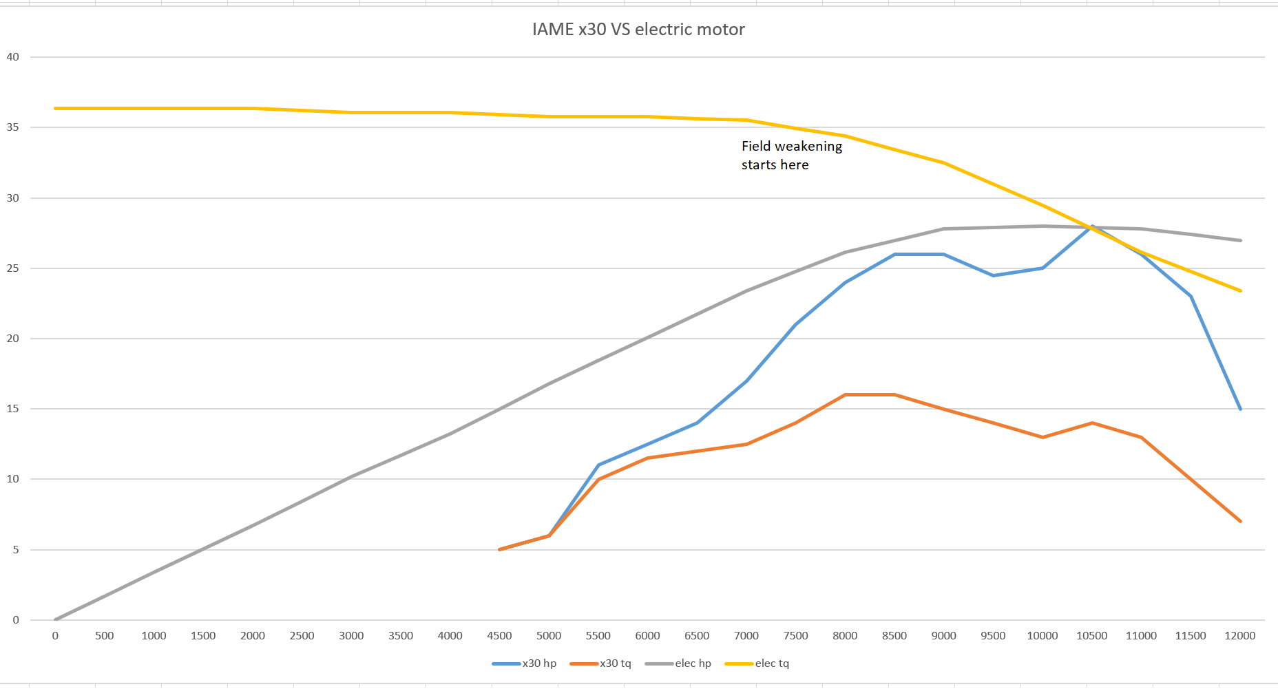
I will describe AC controllers / inverters here as that is what I have researched. An AC controller has both continuous and peak ratings for output currents, voltage ranges for DC (battery) supply, and a peak AC voltage range (minimum being near zero). The controller has to match the requirements of the motor for peak voltage, possibly current (same or less), and rotor position detection. If the motor is rated at 144v and 250 Amps, you want a controller that can deliver the full 144v at the end of the race at the current level required to match the target engine (last straight condition). If the controller (and/or the battery feeding it) cannot supply the full voltage, then the motor speed is reduced. Field weakening can make up for a lack of voltage somewhat, but only at a high cost of current drain from the battery.
AC motor controllers create 3-phase AC from the DC input by chopping up the DC into very short pulses exactly timed to correspond to the position of the motor’s rotor. Here’s a video that explains this concept quite well in the context of stationary Variable Frequency Drives, which are essentially simpler versions of a traction motor controller without the initial AC to DC conversion:
Voltage
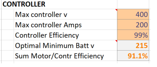
Something very important to note here is that the voltage input IS NOT the same as the voltage output. You cannot put in 144v of DC and expect to get 144v of AC out, you need more DC voltage than AC to hit your target. The formula to compute what the battery needs to supply voltage wise is:
Motor voltage / SQRT(2) * 0.95
For the example 144v motor we would want a minimum voltage from the battery of:
144v / SQRT(2) * 0.95 = 214.4v
This eliminates a lot of the cheaper low-end controllers. Higher voltage parts cost more money, but give that back in higher efficiency (less battery costs, size, and weight).
Current
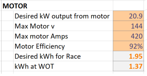
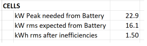
The current input from the battery to get the desired output is dependent on the motor efficiency and the controller efficiency. For our X30 we want 20.9 kW of output at the end of the straight. If our motor is 94% efficient and our selected controller is 95% efficient we get:
94% * 95% = 89.3% efficient combination. Since we want 20.9 kW output, we actually need to input (from the battery):
20.9 kW * (1 / 89.3% ) = 23.4 kW of power.
Since that power is dependent on the battery, high efficiency motors and controllers is highly desired as here 10.7% of that energy is wasted as un-wanted heat.
Controls and the CAN bus
The primary input is of course the accelerator pedal. For most controllers you have a choice between an analog variable resister based unit, or a CAN based unit. I don’t think either one is particularly better, but the CAN unit may be easier to capture data from for latter analysis.
Brake input is next. Depending on the State Of Charge (SOC) of the battery and temperature, you could use regeneration to put power back into the battery before the physical brakes take effect, or in combination. I say SOC and temperature because at the very start the battery will be full, and cannot accept more charge.
Modes: “Park”, Drive, Reverse. Yes you can have electrical reverse. Handy for off-track excursions.
Emergency Stop. Cuts power for safety, usually with a large switch. I am considering using a dead-man switch lead like those with watercraft in case I am ejected from the kart, rendering it safe by default.
Cooling
Some of the choices have air cooling, some have optional cooling plates for water, and some are built-in with water cooling. For short races, I may be able to get away with just air cooling since I will not be running any of the choices at more than 100A.
Programming
All controllers need to be programmed to work with the specific motor you choose and the BMS so it knows the state of the battery. Through whichever interface is provided, you can “tune” the motor to limit how much current and voltage you wish to provide to make the battery last. Many have at least two modes that could be used for say, normal lapping and (extra current) push to pass - much like Formula E or Indycar.
Output
Since all controllers of this caliber now use the CAN bus, any information on that can be displayed by either dedicated displays or old phones / tablets. Readability is important, but honestly having just the SOC and any temperature warnings are all anyone can hope to monitor while racing. Recording the CAN bus messages for later analysis is very nice to have to see how the entire system is working together, or where faults are occurring.
Choices…
There are several mid-voltage controllers to choose from. Here on the ones on my list:
DC Voltage Range, Continuous current, Make and model, URL
50-420v, 300A, Cascadia Motion RM100DX - https://www.cascadiamotion.com/rm-family-medium-volume.html
50-400v, 300A, Cascadia Reinhart PM100DX - https://www.cascadiamotion.com/pm-family-low-volume.html
128-400v, 200A, Sevcon gen5s9 - http://www.sevcon.com/products/high-voltage-controllers/gen5-s9/
50-400v, 210A, YASA Si400 - https://www.yasa.com/controllers/
?-400v, 300A, Axiom 100+kW (open source design not yet in regular production) - https://hackaday.io/project/164932-axiom-100kw-motor-controller
200-425v, 400A, Scott Drive 100 - http://scottdrive.co.nz/Scottdrive100.html
I am undecided on which one to use yet. The controller, BMS, and Charger (when charging) need to all be able to communicate to keep everything safe and in check at all times so interoperability is key.
Next time, the Battery…