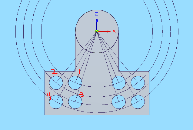
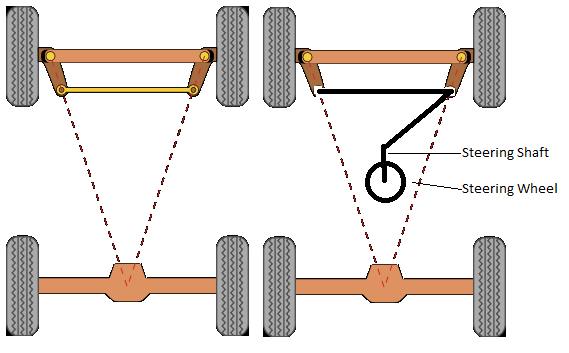
In short, its another way of changing Ackermann. The below picture might help, and I’ve numbered the different setting points on my randomly drawn steering shaft.
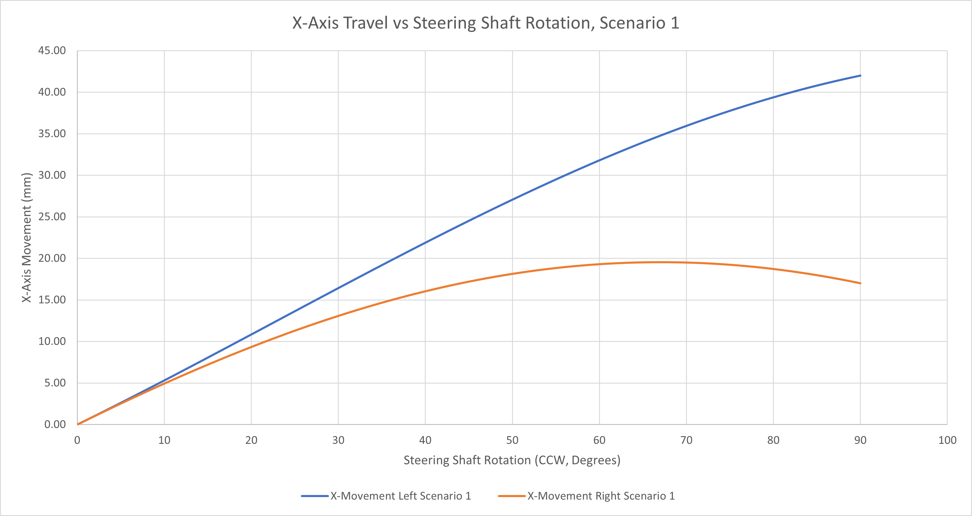
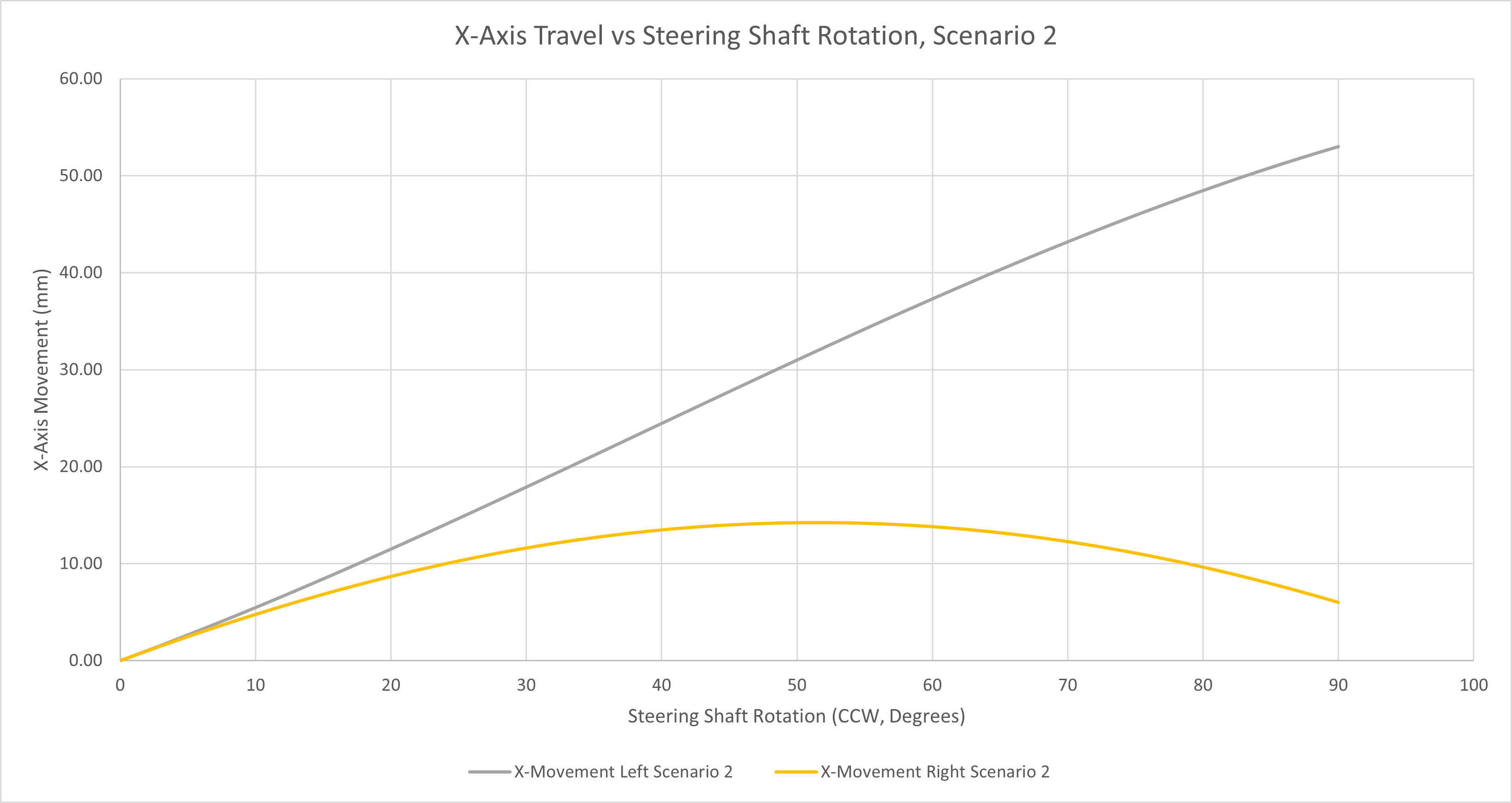
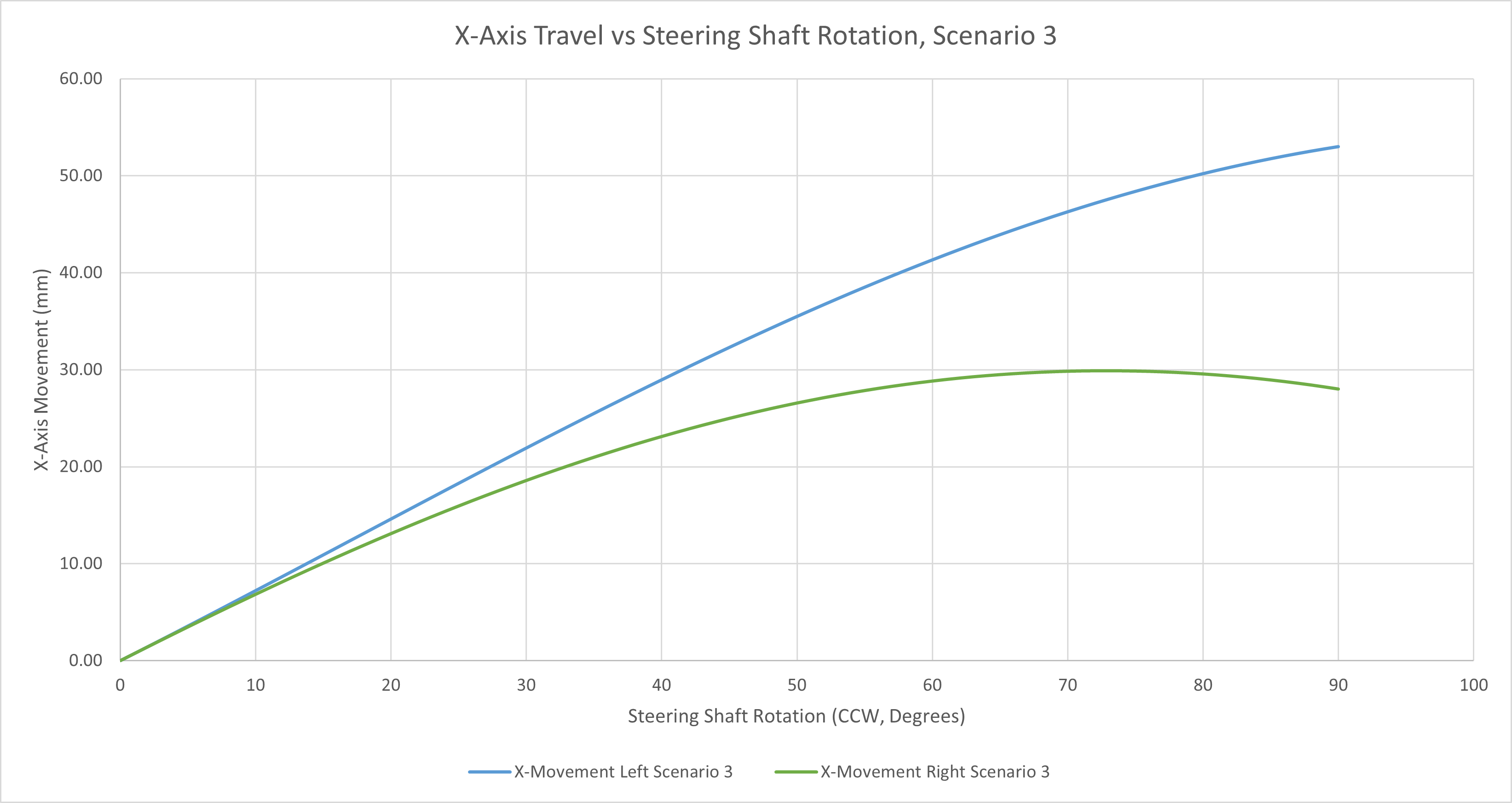
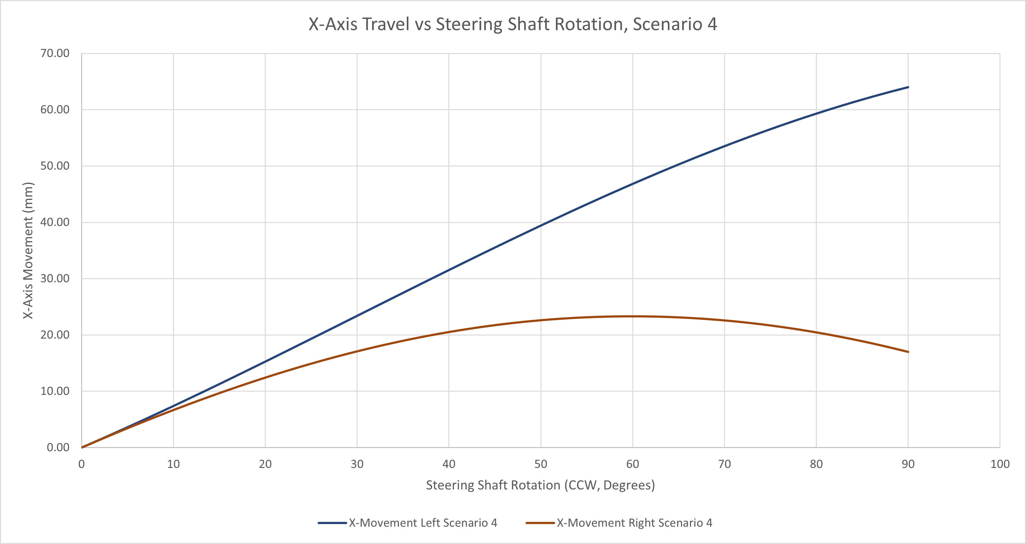
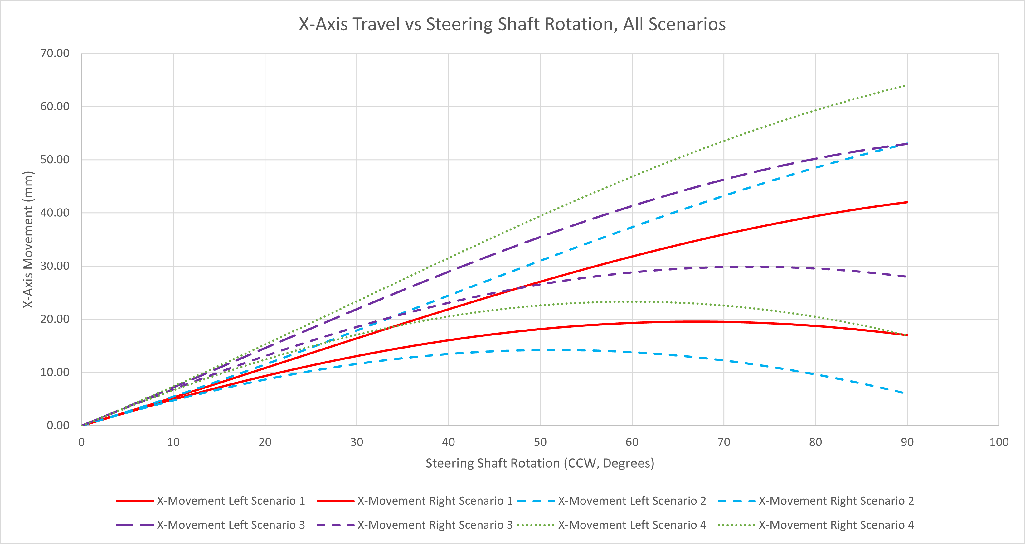
You can see the path that the mounting points are going to follow as the wheel is turned. If you can imagine just the distance left to right that each setup will travel as the steering wheel is rotated, you can see the outer points (2 and 4) have “more” (if we define more as a bigger difference between the outer and inner wheel) Ackermann than the inner ones (1 and 3). You can see that happen on the graphs below that the outer setups diverge faster than the inner.
Its kind of confusing, but here’s a graph with all the setups. Since this is turning the wheel left, the left wheel will always turn more than the right, which makes it the upper line on all graphs.
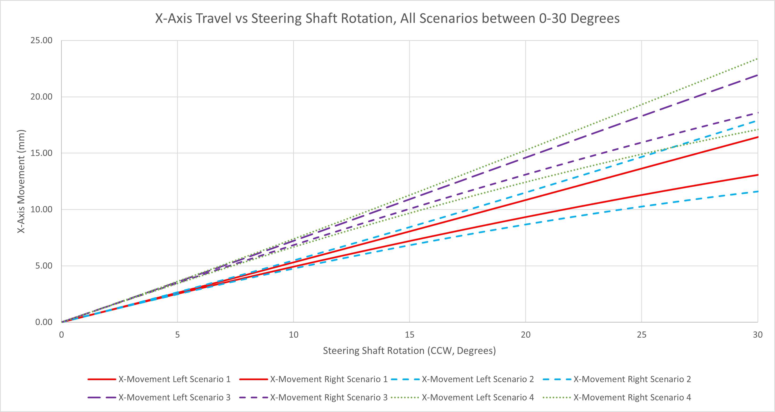
Now remember, most of the time we’re not turning the wheel 90 degrees (that ain’t fast), so if you zoom in on the 0-30 degree range you can see why using lower holes on the steering shaft increases steering effort since you’re moving the tie rods more per steering wheel angle.
Good stuff. I almost never adjust Ackermann. And I almost always leave the tie-rods in the bottom holes on the shaft (3). For drivers with fast hands who are constantly over-driving, I move the tie-rods up to (1) sometimes.
On my Birel’s (It may be different on other models) there is no adjustment on the Spindles at all. Ackerman is only able to adjusted on the steering shaft, and if I change it, it is purely a leverage change, ie the holes further from the shaft will make the steering heavier and the ones closest will make it lighter.
The idea of changing the ackerman rate is never considered at all… haha
Maybe I should start some strength training…
Also for anyone wondering
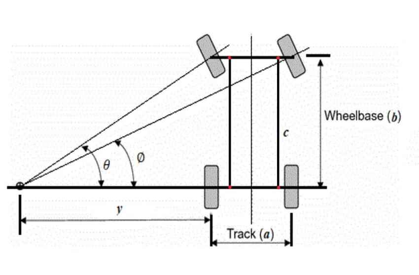
Ackerman - An elegant and simple mechanism to approximate ideal steering was patented in England in 1818 by Rudolph Ackerman, and though it is named after him , the actual inventor was a German carriage builder called Georg Lankensperger who designed it two years earlier.
The Kart Republic’s are the same, 3 options on the steering column, one location on the spindle.
Also one thing to keep in mind when thinkingabout ackerman, you adjust the ackerman when you adjust the steering column height as well. Moving the steering wheel up/down changes the angle the tie rods sit at and affects both the ackerman and steering rate.
Is there a calc sheet or modelling tool available? My CRG is pretty simple. Steering column is in the standard lower holes, and my spindle have three holes as per your illustration. Only thing is on my spindles the holes are straighter to the axle line and not pointing to the front of the kart.
I had the tie rods in the far outside hole on the spindles but moved them to the middle hole which are inter-drilled holes like the Ionic Edge spindles pasted below. Not as close together as the Ionic Edge spindles but still not individual holes.
For the life of my noob karting brain, I can’t see how this would make a noticeable difference. Hence my question about how to visualise the change. I’m not an experienced driver to even tell you what the change did for the handling.
Hi Harjit, I apologize but I don’t understand the question. Are you asking for feedback from people that adjust ackermann frequently how/why they are adjusting it and what effects it may have?
If it helps, from my experience I will “reduce” Ackermann (usually using lower holes on steering column or the holes closer to the tie rod ends on the spindles) when I’m looking for a stronger/faster jacking effect on turn-in. I will say that most would refer to this as “increasing” Ackermann, just as an FYI. It’s not something I usually mess with though, to be honest.
The “pitman arm” (steering column arm pointing down) is the lever of effort. That’s why when you move the tie rods ‘up’ it gets easier to steer – the steering wheel diameter can more easily overpower the shorter pitman arm. Also note the current trend toward bigger steering wheels…
As the pitman arm position is longer, there is more ‘throw’, therefore the spindles move more for the same wheel input. This is why TJ calms his ‘nervous drivers’ with less throw – their actions do less, whether they want them to or not…
Also note that as the motion of the pitman arm approaches 45° and beyond, the motion of the tie rod is ‘wasted’ in vertical motion rather than moving the spindle further out or in… Therefore, the turning rate is diminished at the edges of travel. In some cases, particularly 90’s karts, turning the wheel too far results in the inner wheel begining a progression back TOWARD the chassis… This seemed only helpful while doing the 1 wheel direct-drive dance to the grid…
It would be interesting to see what a non-adjustable ackermann no KPI kart would do… FWIW, I seem to recall the diagram for ‘proper’ ackermann plots a line from the spindle kingpin to the center of the rear axle. If I find it, I’ll paste here…
I think the no KPI part would cause some tough handling. I’d need to do the math, but I’m pretty sure the ackermann needs to be paired with KPI for the caster changes on each side to work out.
In that diagram the steering shaft is going to move both spindles equally. Keep in mind that the tie rod spacing to the steering shaft will affect the ackermann as well.
According to Mayko Pipe and Shark kart designer and builder Al Nunley (RIP), his kart with no KPI handled just fine as was winningly fast. This was in the late 70s, early 80s, I’d imagine, and American karting scene.
The development cycle was considerably advanced ‘over the pond,’ as Birel, Tony, and CRG (and various other Italian boutique brands, advanced chassis design and optimized the front end. This culminated in the Swiss Hutless ‘dynamic bend’ waist, which is effectively what all karts use today. And American karts have gravitated to the wider frame rails that Euros have had for some time. I’m sure someone in the mix has tried 0 KPI, and all the camber / caster variants. I think having less KPI would lighten steering effort also.
If someone were to take a modern sprint chassis and affix two heim joints for spindle carriers a la the dirt kart world, we could test all these things…
Thanks again for your posts David. I’m still in a quandary about the available tie rod holes and the effect it would have.
Best I can advise is the attached sketch. I have a CRG, it has 3 holes in a straight line along the steering blade on each side down the edge. It also has 3 distinct holes on the same horizontal plane on the stub / steering arm. At full lock these 3 steering arm holes are at a 45 degree slant. On the left steering arm full left is the outer hole is closer towards the rear of the kart, but contrary on full right lock the inside hole is closest to the rear of the kart.
I’m just trying to understand how each of the nine possible hole combinations affect the steering feel and handling characteristics. I’m thinking I would like a less sensitive / twitchy kart than a razor edge drive.
If anyone can provide references or the like it woul be appreciated.
Switching between holes (1) (2) or (3) will in general change the amount of steering effort required, and the maximum amount of angle that the outside tire can turn. (3) will require the most amount of steering effort, but also allows for the most amount of tire turn. Generally speaking, I would start at (2). The ackermann change on the steering shaft is fairly small when the holes are all in a line like that, it’s more about steering effort.
Switching between holes (A) (B) or (C) will change the ackermann directly. (C) will have the most ackermann (wheels diverge the most with turning of the steering wheel). I would start with (C) if possible with your current tie rods. If not, go with (B) and try out (A) when at the track to feel the difference.
TL;DR: jacking is a function of Ackerman, so it comes down to more than just outright steering speed although steering speed and effort certainly matter.
Karting is unique in that the kinpin inclination is huge and the kart relies on each front wheel changing the cross-weight as a function of steering input. This cross-weight function changes depending on Ackerman, so, even though there is one ideal Ackerman for getting around a geometric arc, there huge differences in the jacking you get for different Ackerman setups.
The outside tire is the most weighted and has the most say in what kind of arc you carve, but the inside tire’s angle depends on initial toe and your Ackerman gain. Increasing Ackerman increases the jacking effect for a given outside tire angle. This increases effort as well as twisting the chassis more. Secondarily, it changes how the kart scrubs speed since that inside front tire acts like a anchor trying to scrub speed since it is sliding more than the outside front.
If you have the patience, interest, and scales, you can sit in a kart and measure the corner weights when pointed straight and when turning some angle. Then measure this change for different spindle positions. I have not personally done this due to a lack of time and scales, but it could be neat.