Thanks for answering the intended question, lol. First sentence in your reply is spoken like a true engine builder, and I should have seen that coming ![]()
1 Like
I sold that business, so I am free and clear now!
Just gave me flashbacks from all the times I’ve asked Mark Harrison “are guys doing xxx” and gotten back the old “I can’t speak for what others are doing, just how we build 'em” ![]()
What’s the largest delta on the dyno that you’ve seen from a head (doesn’t have to mean you know who worked on it ![]() ) that was taken down to the legal limit?
) that was taken down to the legal limit?
Would accept answers from anyone else willing to add to the conversation. @CrocIndy
1 Like
One change like that… I will say basically 0.00 hp
Every grey area trick I know combined (not cheating, but blueprinting), Lets say 0.05 to 0.1hp.
Keep in mind the spread engine to engine is 0.3 hp
Disclaimer: These numbers are not exact, but examples for scope and range.
3 Likes
Thanks! That’s helpful context.
Derek’s numbers sound about right.
Blatantly cheating pop up and head depth don’t really do much either. I have a head that has no shallow shelf left on it And it doesn’t change anything.
Can you share information on how you did the head flattening? I’m not an engine builder or machinist.
I’m wondering if you did it in a mill? How did you set up the head so that you had the final plane you wanted parallel to the cutter’s plane?
I’m sure my terminology is all wrong.
Thanks for educating me.
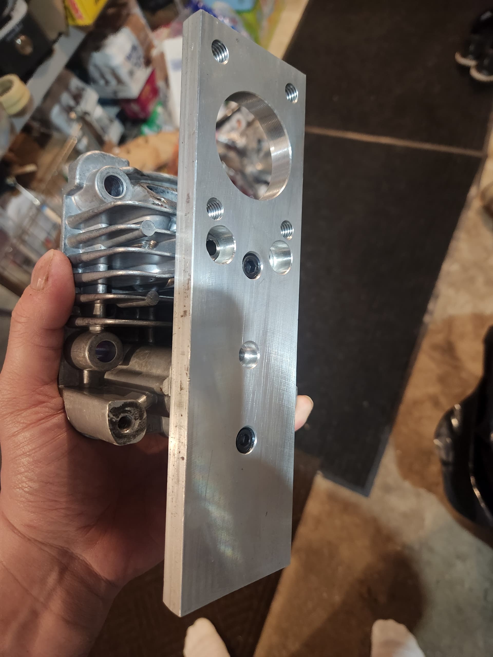
Yes, it was done in a milling machine. Setup was fairly straightforward on this head, because the gasket face and the top of the head are parallel to each other. I started by making a simple fixture from a piece of aluminum I had around the shop. Flycut the piece top and bottom to make it flat and parallel and drilled holes in it, so i can bolt it to the top of the head, then I clamped the fixture plate flat to the mill table.
1 Like
I was wondering when you called out 6 thou. The edges tend to curl inward which pushes the gasket surface up overall which is why we can re-true up the surface without overall messing up the combustion chamber depth
That was a total of 6 thousandths from the initial contact, which like you said was at the edge. The immediate area around the combustion chamber didnt clean up until the last 2 thou. I checked the rulebook for head specs, and they only call out 0.031" to the shallow spot, and 0.342" to the middle of the chamber. I measured both with a depth mic, and i was above those minimum measurements. Who knows, maybe this head is just a touch bigger than most to start with?
Harkening back to the animal and WF days we always trued them up on a surface plate with wet sanding. When the WF engines started coming with the heat extractor piece on the exhaust corner head bolt we started noticing more warping. We started yanking that piece and got reduced warping. Was totally backwards of what theoretically should happen.
If I didnt have access to a machine shop, I’d also lap them in to true them up. Nothing wrong with that at all.