Looking good! No logo required, this is a POC prototype. I’m sure it will need refinements.
Better get some more followers
I will follow Dom in asking for Sponsorship. ![]()
Great job so far BTW!!
3 Likes
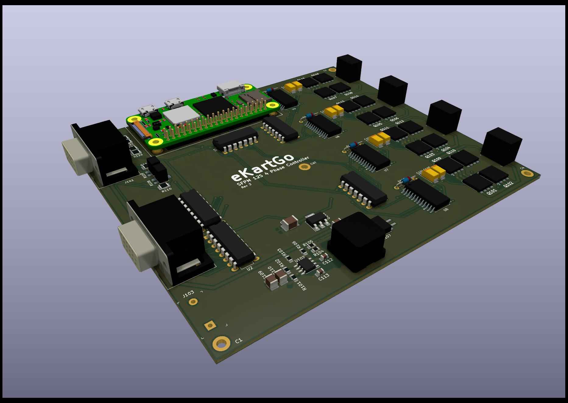
I found a couple of rookie KiCad mistakes on the rev2 PCB. Nothing I can’t patch, but here is a rendering of the rev3 board as it sits with the Raspberry Pi 2W attached. A few components don’t have 3D models, but it’s pretty complete. Slowly getting better with this software.
My mind is still blown on just how small some of these high power components are compared to the '80-90s TO-220 stuff I earned my degree with.
Now for all the parts to eventually get here, some that seem to be on VERY slow boats from Taiwan. ![]() I may still beat the Georgia motor company at this rate. Whichever is available first will go on the kart.
I may still beat the Georgia motor company at this rate. Whichever is available first will go on the kart.
3 Likes
Is there a reason you designate the mounting holes as C1 to C4? C usually reserved for cap only.
That’s what I think KiCad inserted them as, so I just left it. It doesn’t matter to me, obviously not a capacitor. ![]()
July 2022 update
The rev2 boards arrived in the mail. Good experience overall, and I was able to test fit components to ensure what the KiCAD templates show and what the physical part are - match. But that is REALLY an old design now. ![]()
Biggest change - Out with the Raspberry Pi processors and boards. Although they have 4 cores, and you can tell the OS to not run on certain ones, it doesn’t totally obey. Spurious interrupts screwed up my timing on these dedicated cores, so I gave up and looked for an alternative.
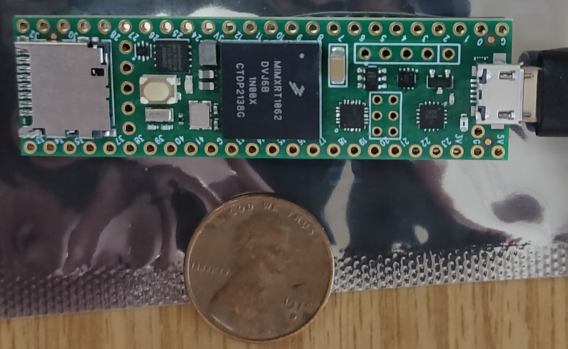
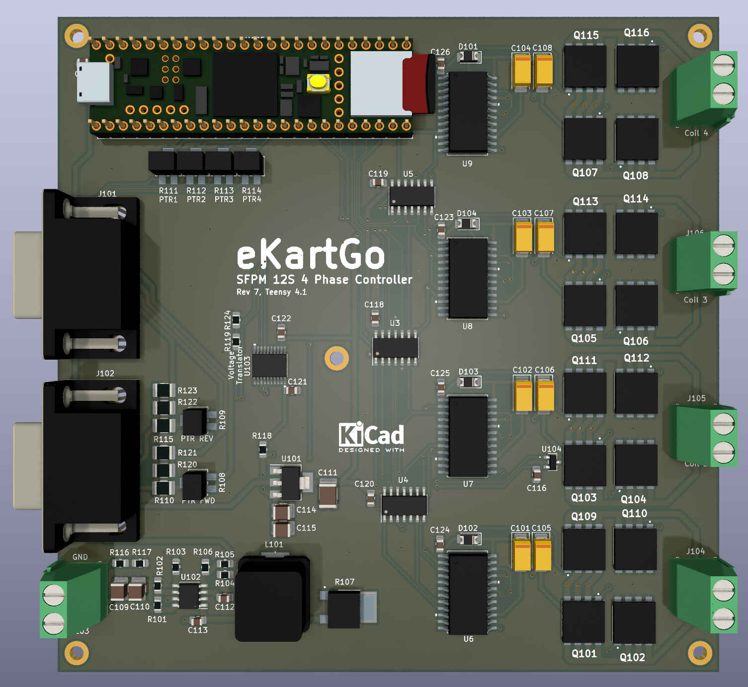
Now I am using a Teensy (they really are, see picture below) 4.1 microcontroller. It runs at 600 Mhz and runs rings around the ARM processor. Plus it has true hardware interrupts on pins - which is really nice and easier than using polling loops, and on-board ADC so I can drop that chip and get faster reads. Software support for most things is pretty good, although the whole Arduino code building is a bit odd compared to the normal gcc stuff. The board is now up to rev7. I currently have support included for UART, I2C, and physical switches (no touch screen stuff for a kart) I/O. I added a temperature sensor for the FETs as well as a battery voltage input to keep tabs on it. Display will be a 20x4 LCD as the eInk displays don’t work with high vibration (go figure) and you can still read it in direct sunlight. I may add CANbus as well to tap into BMS info.
Software dev is well underway (C code), and essentially complete as far as the basic functionality goes. This weekend I plan to hook it up to the plastic motor to verify the interrupt driven timing from the IR LED / phototransistor sets work as designed - at least as fast as my drill will turn it. Also have a Hall-effect throttle sensor on the way, as that should prove reliable as an automotive part and is also water tight unlike a most pot sensors.
Size photo:
Current board:
1 Like
Anyone know what a MyChron 5 needs to see as an input for the RPM inductive pickup?
I’d like to simulate a spark output from my motor controller to feed the RPM to the MyChron. I see that it used a 50Hz sampling rate - but what do I need to create for it to register (and not turn off)?
PS - if you also happen to know what a temperature sensor returns so I can create that as an output as well mainly for an alarm, that would be great.
{EDIT} Of course what would be better is to just connect into the CANbus it has and tell it the RPM, temperature, etc. I need to just contact AIM, hopefully they won’t just dismiss my questions.
RPM pick up usually just a simple version of inductive clamp or capacitive, then go through conditioning circuit to uC. Generate a high voltage short pulse should be able to do the trick.
AIM EGT is a thermocouples, most likely a type K. So a small voltage mV range will be generated across the wire when the sensor is heated up. Different sensor has a different range or reading, heat the sensor up and measure with a multimeter. There is also a chance they use a thermistor type sensor to measure voltage.
Are you looking to record motor RPM based on the controller, or just pickup a pulse to keep the MyChron awake?
I don’t think the 5 supports CANBUS, but other AIM models do. Might be easiest to have a hall or VR sensor on the motor output shaft and amplify that pulse such that it’s picked up by the inductive sensor on the Mychron.
Record. Keep alive is easier, but having the RPM is nice to have for gearing comparisons.
According to the docs, the 5 and 5S (not sure about the 4) use CANbus for the PC I/O connector on the back. The software would need to be changed to support this use of course. I emailed support to ask if pushing data to it via CANbus would be a future possibility for an e-kart version of the MyChron (same hardware, different code).
3 Likes
First half August update…
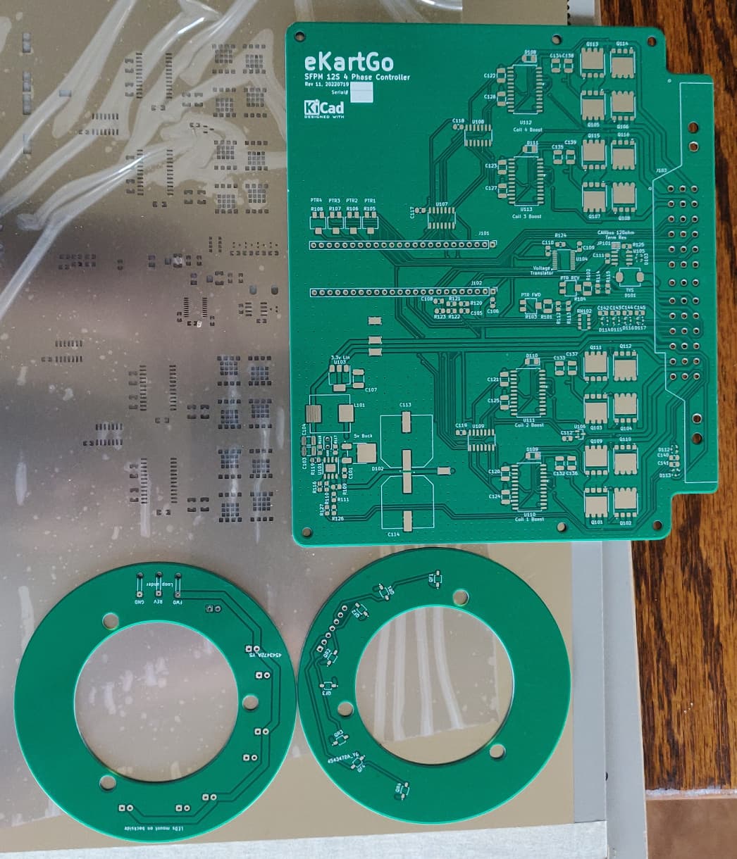
The PCBs arrived! For some reason the silkscreen for the test points didn’t print (looks like a footprint issue), but other than that they look great. Shown with solder paste mask (reversed).
No feedback from AIM on the MyChron issue. So I’ll just punt that for now and use a hall sensor pickup as a kludge input.
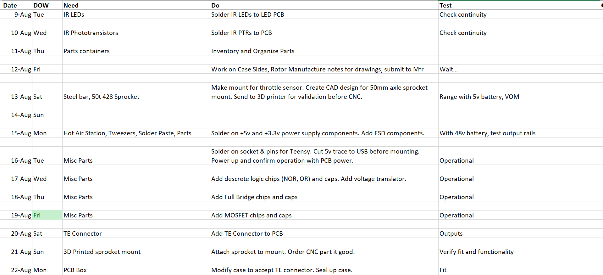
Waiting for the hot air station to arrive to get the parts added. I plan to do it in stages to allow for testing of each component of the overall circuit design. Schedule is probably over optimistic as always, but I can adjust as needed. The goal is continuous progress anyhow, not meeting artificial deadlines.
1 Like
Did everything I could man sorry. I tried waiting for the teacher to come back from Australia to get it done late summer but it doesn’t look like it’s gonna happen. I’ll ship the stock and the mostly finished piece back to you as soon as I can.
Sorry for all the delays, it should’ve been done many months ago
1 Like
Don’t sweat it, I know you tried and gave it your best effort. Stuff happens sometimes and we just have to adjust and move forward.
1 Like
My teacher being fired was not something I was preparing for… nor was the new teacher quitting
Wait, I didn’t realize you were expecting me; I’m afraid I’m going to be late. ![]()
1 Like
Hi Bryan,
Just officially joined the forum after following your project. This is neat stuff ![]()
I have a few thoughts to share. I might be completely off here (I have not looked at every single detail of the past months), so just tell me if I am left field…
How much current Iin & Iout or you expecting in your motor controller? I saw 12s up there so you will be at around 50.4Vmax (@4.2V cell) and about 38.4Vmin (@3.2V cell). For a 31.5kW motor that will give you roughly (assuming eff = 1) → 31500W / 38.4V ~ 820 amps at the controller input. That is quite hardcore for a standard FR4 PCB, even on a multi oz copper… If you are planning to use FR4 you will want to make sure you do not get above around ~130C on the PCB. It will start delaminating at that point. Is this board going to be used as a first phase to test out the control and basic electronic design? Maybe this is the part I am missing…
Additional note, your initial FET selection (NVMTS0D7N06CLTXG) @ 60V Vds seems quite tight for a 50V input. You will certainly get some resonance on the full bridge due to parasitic inductance of your cables etc. Usually max input x2 is recommended to be on the safe side. You will pay a small price in Rdson increase on but that is usually a healthy compromise to avoid failures and the nasty repairs that come with it.
Check this chip this out if you have a chance: TMC4671 - Trinamic. It is quite a neat ASIC that implements full field oriented control that you might be able to utilize for your controller design. It packages a lot of the tricky embedded control stuff in one place. I know you are on another path but I thought I would share.
On a completely different note, do you have updates on the DHX motors? Would you know when they will be available and how much a P40 would got for (roughly).
Thanks for all the amazing work on this project. It is nice to follow. I thought I would share a few notes today that might be helpful. 100% trying to be constructive here ![]()
FG.
2 Likes
Hi… thanks for the questions and feedback.
First off DHX motors. They are making progress and have built a few of the P40s and P60s from what I have seen on their Instagram posts. They are now machine wound, but I’ve seen no indication yet as to when they will be available for general order at a much lower price than the hand-wound Hawk motors. I have hung onto my controller for the P60 hoping this would come through much sooner, but supply chain still seems to be somewhat of a constraint for them. Time to give them another phone call to see how it is going and if they have an ETA on when they will become generally available for purchase and at what price.
As far as my alternate SFPM motor design, yes those FETs and coils will need to take quite a bit of amperage - more than you would normally want to run as you state for use with PWM. Except that they are instead designed to be pulsed only once to enable the flux, and then again to disable the flux from the PM towards the rotor over a 20μs (or less) target switch time each. Even at high RPM (e.g. 40,000), the effective duty cycle is still quite low. Of course this “odd” coil use complicates the coil design balancing all the electrical factors required for a quick switch time, which is why I am still refining the PCB type design for a good compromise based on my (admittedly) limited magnetics knowledge. Every few weeks I test and then modify the design for (usually) better results. I’m not looking for “perfection”, just a reasonable POC motor design I can demonstrate and then go forward with starting a company and hiring mechanical, electronic, and magnetic specialists.
Good morning Bryan,
Thanks for the quick reply! Yeah, these DHX motors have fantastic specs… Let us know what you hear from them. I would love to get my hands on one of them. Power to weight is pretty amazing…
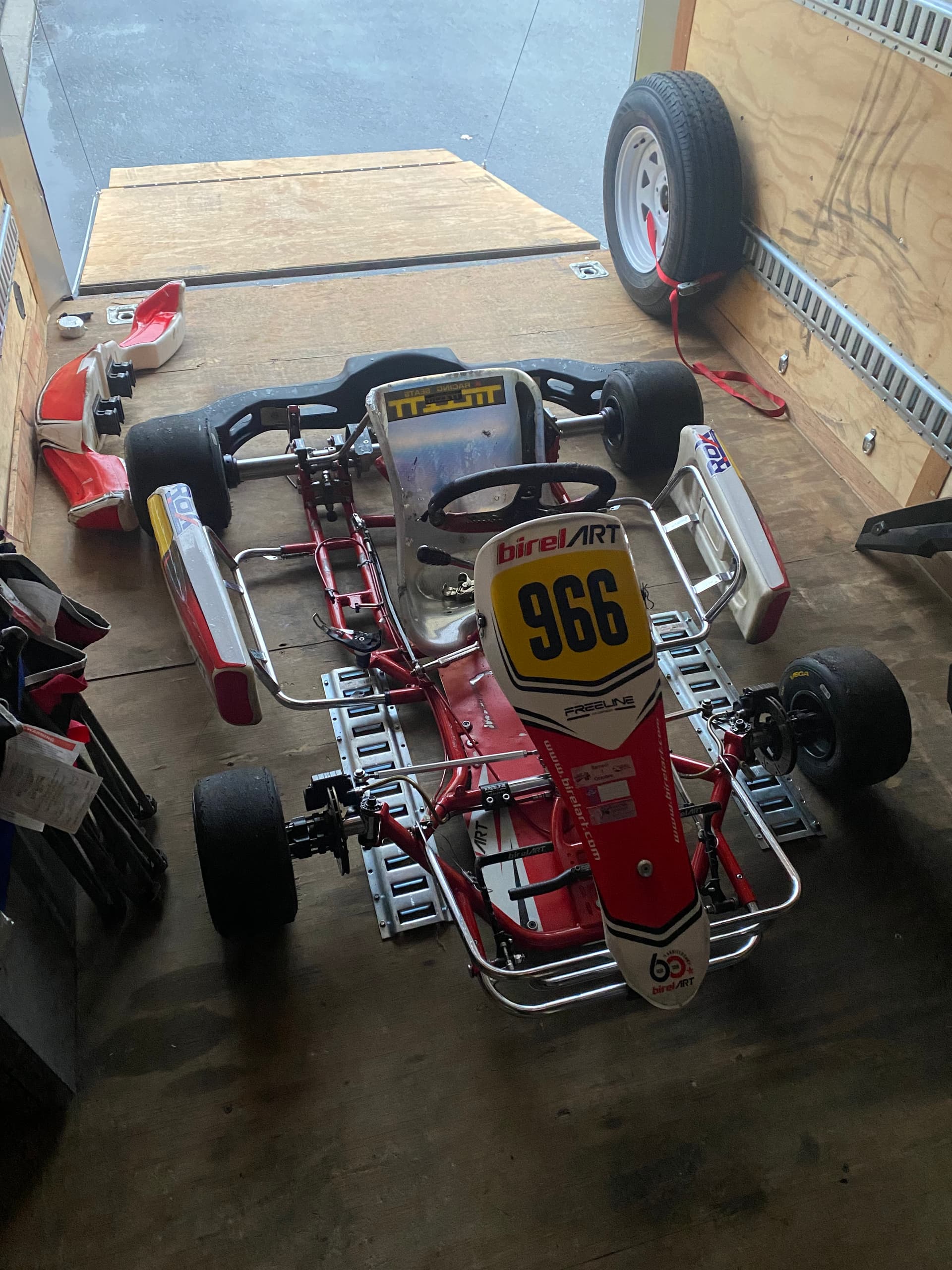
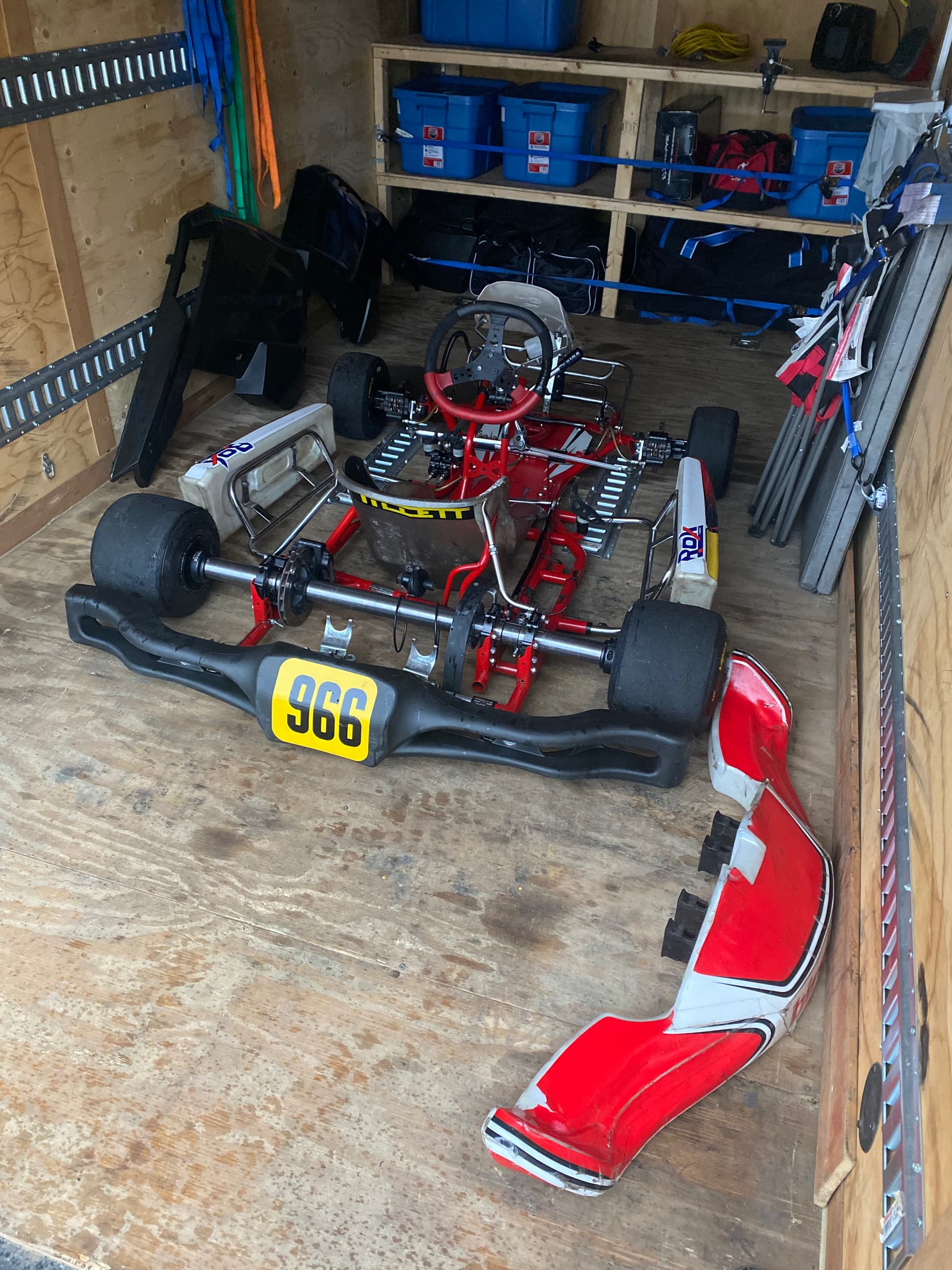
I just started a project myself, very similar to what you have done in the past. I just bought a 2019 Birel shifter chassis and looking to build and electric power system for it. I was initially contemplating buying a BSR 2.0 system… but given the cost… and the fact that it is fun to put together, I thought I would do it myself.
I actually have a ton of questions for you… I went through your gSheet in detail…
Looking at my different setup options, I found the ME1507 (air cooled) to be the most plausible candidate for my build. Simple goal would be to keep up with Rotax Max 125 on lapping sessions, have a battery swap system. The ME1507 is on the heavy side but I figured that with up to 44kW of peak power and 15kW continuous I would have plenty to work with to start. Price is decent, again, ~22kg is on the heavy’ish… What are your thoughts? The BSR setup seems to use a very similar motor (at least the housing is identical)…
I looked at others (like you did in your spreadsheet). The EMRAX are quite neat, but the 188 goes for 3.3kEuros… which is another level. Plus the out-runner design is a bit trickier to safely integrate in the build. I also heard they are quite a nightmare to tune and setup…
I found some chevy spark battery modules, 60aH, 100V, based on A123 lithium nanophosphate cells. Discharge current is plenty good and 60Ah seems about right, maybe slightly high…
Curious to hear from you what motor you would pick?
FG.