We startet with the battery in center , where the Gasolin tank use to be. In the new version of my friends e-kart , it sits on the left side, where the radiator normally is. This setup handles corners so much better, and sucking to the road. When im building my new e-kart this Winter, the battery is going to be on the left side as well.
1 Like
Thanks…
I started with the battery design in the fuel tank area as well - but thanks to the low energy density of batteries there is not enough space.
It’s going to be heavier than I like, but such is the state of batteries at present. I am planning on the ME1302 being temporary, to be replaced with a smaller, lighter and more powerful new DHX unit towards the end of the year. Hopefully for now the weight is somewhat balanced out so that it doesn’t handle poorly. This general arrangement as you said with the battery on left, radiator on right seems to be the best compromise at present.
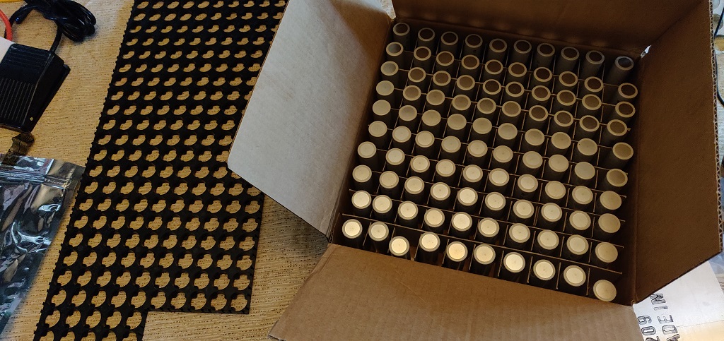
First phase of assembly is the battery pack - Batteries will be here tomorrow (hopefully). Spacers, copper, and nickel by the end of the week. kWeld - ??? RSN
Final layout:

2 Likes
Wow, Bryan, this is an awesome thread.
Great work so far and thanks so much for sharing all of your info inc the spreadsheet. I’ve used it to sense check the setup for a kart that i’m building in the UK. (Motenergy me 1304, sevcon g4s4, lightweight, low capacity 18650 pack 20S 15P changeable between races)
I’ve decided to re-imagine the chassis also, just to add to the already very steep learning curve.
I’ll continue to follow this closely and when i make some good progress, will share back.
Keep up the great work!
Matt
1 Like
Thanks Matt - share what you have as you get there so we can all learn together.
I should have some photos and possibly video up this weekend of the start to the battery build. It’s unfortunately going slower than planed because of various things that seem to come up that need more attention (such as a blown air spring).
In the mean time here is my electrical layout. This is with an Orion2 BMS and Kelly IPS controller.

2 Likes
Some progress on building the pack tonight. One layer’s cells inserted and ready for the busbar and strips. One to go…
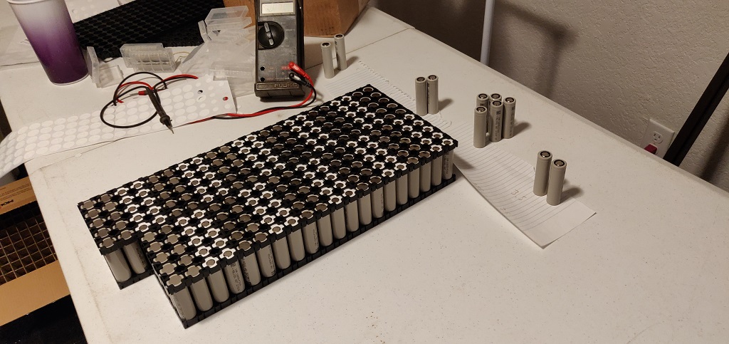
1 Like
Second layer completed… So far 44.1 lbs (20 kg).
Now I need to drill and trim all the copper bus plates.

3 Likes
Out of Curiousity, what kinda pricing per unit do you get when you buy that many 18650?
1 Like
Dom, I paid $3.45 each shipped.
Here’s an assembly time-lapse video. Even sped up it takes a while! 
2 Likes
Battery looks great so far! QQ for you around the configuration:
Did you reject honeycomb cell configuration for any reason?
It seems like a slight space saver, but perhaps slightly harder to work with and less air gap/higher temp in IMO.
Also,
Would you mind if I ask where you source your cell holders and strip/plate for your cell connections?
I’m looking to source cells, holder and strip connections imminently so keen to hear your thought process.
Best,
Matt
Thanks Matt
I went with the grid configuration since I am not completely certain about heat buildup. At TAG speeds I’ll be drawing about 32% of the max C rating. Recommended is to not exceed 50% continuous to keep them from heating up too much. 206 speeds of course is much less at 14% of the max C rating.
I bought the cell holders from Amazon, they are nothing special:
The strips I am using are from Ebay:
Copper plate is from Onlinemetals:
https://www.onlinemetals.com/en/buy/copper/0-032-copper-sheet-110-h02/pid/19857
https://www.onlinemetals.com/en/buy/copper/0-08-copper-sheet-110-h02/pid/19860
Bryan
2 Likes
Updated spreadsheet with some more options for controllers, cells, etc. I have also included a tab with some ekart builders current packs.
2 Likes
Really good stuff. Thanks for compiling this. We may make a change to our final battery pack but we are not sure yet. It will either by 22S/20P or 22S/18P depending on how our load testing goes. Thanks for all that you do for this forum. VenomKarts
1 Like
So the stock KWeld spot welding tips are not going to work, especially on the thick bus bars, for the nickel to cell connections. I think the old STTOS line “bear skins and stone knives” applies here. The holes are 5/8" (roughly 8mm), and although I could make them larger, I’d rather retain more copper.
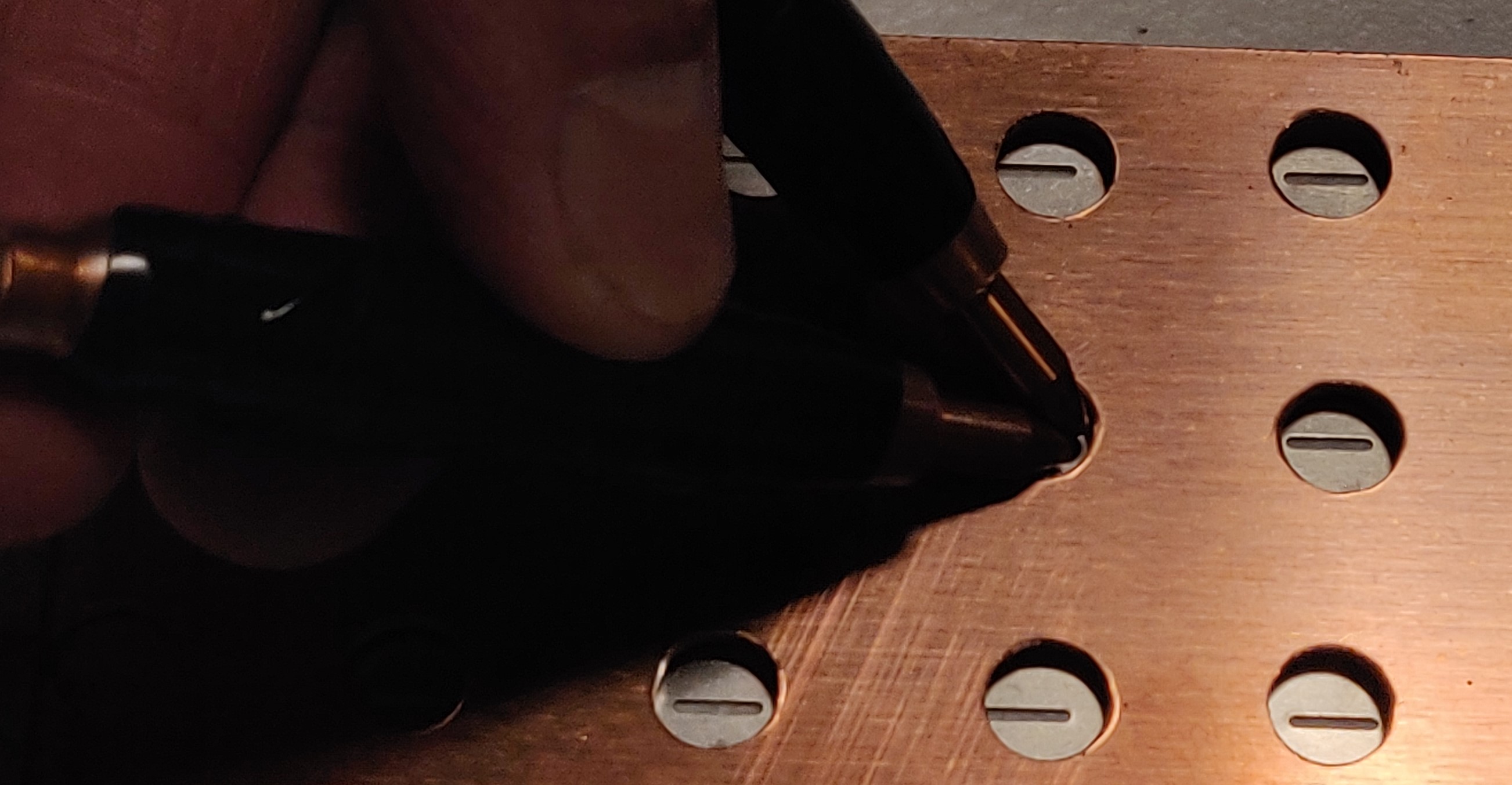
I starting considering various ways to make thinner probes, and then found this video. Easy construction, versatile probe size, etc. Plus cheap.
I plan to try 6 AWG silicone covered copper wire (doubled or trippled up inside the tube) with 3/32" tungsten tips. I will just run the wire out of the “pen” and to the KWeld board. That will let me retain the same size lug as the OEM one for easy mounting, while also reducing the heat of the wire.
1 Like

This is the group I will initially be running with. I’ll have to force my self to set the max current on the controller to not over-run anyone. It will just be too tempting…
This is the bus-stop configuration, normally the karts run out into the banked turn at the end. This track and shifter karts don’t really mix well, too many tight slow corners you are always in the wrong gear for.
1 Like
The basic worry is overheating? Presumably lotta cornering eats up more power and heats things up with the accel/decel?
Sorry if I gave you that impression. With 206 speeds I anticipate no issue with overheating.
Rather I will be running as a local option provisional entry. If I keep the controller unbound I could most likely go from last to first in one straight if I see red. But that is not the goal. I’ll need to be competitive with out ticking others off.
For this first step I want to show to the organization that electric karts are safe, and can be power restricted to reasonably match existing ICE classes. That will hopefully increase interest in going with bolt-on kits like Gary’s Venomkart ones (near future). With a minimum of three like karts per race we can then have a separate EKart class.
1 Like
Do you plan on modeling the LO206 acceleration curves as well as limiting your top speed. I know with electric motors and modern speed controllers there is some tunability, but I think it would be unfair to rocket off the line or out of the corners just to top out at the same speed. Perhaps using several dyno sheets you can somewhat mirror the characteristics of the LO206. Of course in the future Tech would require a laptop or something to plug in and verify you haven’t tampered with it or that you do not have a way of remotely toggling between say acceleration map A vs B like Formula One does with the Hybrid Battery Boost. Other option might be a sealed controller that cannot be altered and limits peak amps/volts.
1 Like
No. For the reasonably sized (and priced) units for use on a kart they are quite simplistic in the programming realm so I’ll mainly be limiting the maximum power output which dulls the torque as well as limits the total HP. My 15 year old MKIV VW/Bosch ECU is much more advanced in these regards with programmable 3D load curve maps and throttle response maps.
While being provisional I’ll have to toe a fine line between being racy and being reasonable as to not upset the others. I won’t be getting any points, etc. so this is just for fun now anyhow. Fun for me being doing something that hasn’t been done before, without any rules other than for safety.
So I’ll start off slow with the 206 class, gather data, and then when I’m ready to do so adjust the settings and move to the TAG 2-stroke class where the higher weight will make it overall more challenging to be competitive without any artificial limits.
1 Like
Totally agree that this is an excellent strategy. You will get great test data and generate interest in E-Karts. You’re doing a fantastic job and we love following your story. Gary -VenomKarts
1 Like