Leopard power pack issue

Hello everyone, im having an issue that im hoping someone can help with. I have an older italkart with pre08 Iame. My issue just started the other day. If i connect the battery the kart wants to continually crank over. My issue is in the powerpack. I checked the switch and it appears to be working. How can i fix this open circuit ? Can i bypass the the powerpack and just wire a relay in the starter circuit? Any help would be greatly appreciated

Sounds like the relay is stuck open? That should be replaceable from what I remember.

Would you happen to know where its located?

Its located inside the power pack:
07 leopard power pack

You may have to try to match the relay with something more common from an autoparts store. There should be some information stamped on it.

Thank you Greg. I looked inside., and didnt see a relay that resembles the one in the illustration. Do you know which one it is? How do i get into the coating that the board is incased in. Thank you for your time.


From the looks of it, I would say the small rectangular chip-set with five metal contacts at the base and a nut at the top is an Integrated Micro Switch responsible for triggering the starter motor. You can verify this by checking continuity and voltage outputs.

Care of James from https:

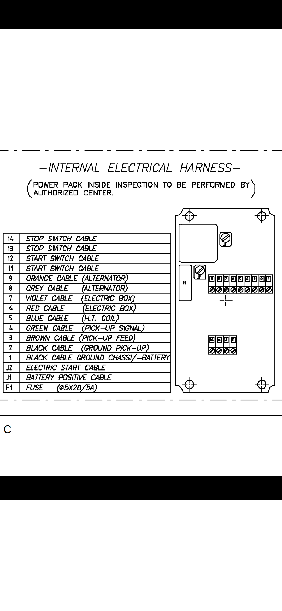
Here is the data sheet on the Micro Switch:

The prongs at the bottom in your picture are 1 - 5 (left to right), where 1 and 5 are (+) outputs to your load (the starter), 3 is (+) from the battery, 2 is your switch (triggered by grounding circuit) and 4 is used for diagnostic feedback (unless you are knowledgeable about proportional currents to loads you can leave this alone for now).

Using a basic Multimeter or even a test light, you can check the prongs for voltage. Unplug the starter from the power box and connect the battery to power box. Connect the ground for the tester to the (-) terminal on the battery and check for voltage at prong 3 first (middle). Should be equal to whatever battery voltage is (12V +). Next check voltage at prongs 1 and 5 (far left & far right). Should be zero volts with starter trigger NOT pressed and (12V + ish) with starter trigger pressed. If it has voltage and starter trigger is not pressed, the micro switch may be bad.

One more step to verify. You will need to disconnect the (+) lead on the battery and use a multimeter or Ohms meter to measure continuity from prong 2 (second from left) to the negative terminal at the battery. There should be no continuity when the starter button is NOT pushed and continuity when the starter button is pushed. If there is continuity without pushing he starter button, you have a bad starter button or short to ground somewhere in that circuit.

Let me know what you find.

Greetings Greg, thank you again for your help and for being so clear and concise with your instruction. When it come to electrical troubleshooting and testing i havent a clue and its all greek to me me. So here is the results. First test, starter disconnected power to box, #3 pin had continuity with no button pressed. Second test, pins #1 & #5 check for continuity, there was none present in the resting state and continuity was present while the starter button was pressed. Im assuming that means my switch is faulty? Ill be looking forward to hearing from you with further instructions on how i should proceed. Thanks again Greg, your knowledge is greatly appreciated. -

With everything being potted I’m not sure if it’s worth trying to replace components. Might be best to replace the entire unit?

False. That is what is supposed to happen. Power is sent through #1 & #5 only when starter button is pressed. The fault is somewhere else. Does J2 have power with and without Starter Button pushed?

I suggest you recheck the connections to all of wires going into the box and make sure they are connected to the correct things (reference Internal Electrical Harness Diagram above). It may be tedious, but you will likely find something in the wrong spot. Are there any shops around you that you can take it to? Perhaps someone with more experience can help identify the problem.

Im sorry Greg i meant to say that i am showing constant voltage 12v while the starter button is not pressed at pins 1&5.

Are you using a multi-meter or test light? If its a multi-meter, disconnect battery and set to Ohms.

Check for continuity between pins 3 & 1 and 3 & 5. Still have continuity with no power connected?

If yes, its a bad micro switch.

If no, you have a fault in your starter button circuit. Circuit on pin 2 triggers power to 1 & 5 by grounding pin 2 when connected to a power source.

Quick check for starter switch circuit:

  • Still on Ohms, connect one lead of the tester to pin 2 and second lead of tester to negative wire to battery harness.

  • Test for continuity with switch off and pressed.

  • If you have continuity for both, your switch “circuit” is at fault.

  • If faulty, you can narrow the search by breaking the circuit into smaller sections. Example, pin 2 to terminal into start button. Terminals into start button to out of start button. Out of start button to negative battery wire (test with and without Start Button Pressed).

If all checks out (have continuity), then move one of your tester leads from negative battery wire to a good ground on the chassis and recheck each section (pin 2, into starter button, out of starter button, negative battery connection at end of harness).

If you still have continuity, you will have to break the circuit up, by disconnecting each section from the system. Unplug the wires for the starter button. Disconnect the wires to the bus bar for # 1 and #2 (both are at far right in your picture on the long strip below the micro switch. Note: Thicker Black Wire goes to #1).

Remember, you are looking for a short to ground. That means there is a connection somewhere between pin #2 on the micro switch back to a common grounding source (terminal 1 or 2 on the bus bar) triggering the starter circuit.

With the circuit broken, check if you have continuity between pin #2 and Terminals #1 & #2 on the bus bar.
If yes, it could be a short in the Power Box. Replace the Power Box.

If no, keep checking each section of circuit by testing either end of the section itself and then one end of section to a chassis ground. Likely when testing each section alone it will have continuity, but if you find continuity between any given section and chassis ground you will need to thoroughly check that section for damaged insulation on the wires that would cause it to ground out to the chassis somewhere or back to the common ground harness. On the Bus Bar,Terminal #1 is the Common Ground for the entire system. Terminal #2 should be the ground for your Stator/Alternator.

If all else fails, you can do as James suggested and find another Power Box/Harness.

Thanks! Thats alot to do. So far between 1&3 ive got a reading 0.3 ohms and 3&5 is reading 0.3 ohms with no power applied. Starter switch circuit only has continuity when button is pressed. Same for kill switch. When testing pin 2 and neg battery set on ohms i get no reading while button is pressed and with not pressed i ger zero reading as well. Will perform rest of procedures and report back shortly.

What can i do if switch is obsolete?

Have not conpleted all test at this time. I will have tine shortly

Hello Sir, would you happen to know if there is a fix for relay that is stuck open with the leopard power packs?
Thank you

Hold up. Are getting zero ohms or no reading when testing between pin #2 and a ground on that circuit? Ohms is always a decimal. If it reads 0.000, you may have to switch to a smaller measure like Kilo-Ohms to see a reading. If it blank, you have no continuity. Also worth noting, on my MY09 Leopard, the starter still had power going to it, even with the Starter Switch off. It was just a trickle though and not enough to engage the starter, but enough to drain the battery if I left it connected to the system while not in use. Starter needs voltage and amperage to turn over. That’s another rabbit hole.

On a side note, you can google shop part numbers and find many obsolete parts available for cheap:Google Shopping – Product not found

Ive got continuity between 1&3 3&5 when no button is pressed

How do i get to the soldering pins to desolder and replace. Switch? Scrape off with xacto?

Ive got a BTS555 on the way

I would think you could just cut them between the chipset and the board, then solder the new pins to the tops of the old ones. Just don’t heat them so much that you unsolder the bases of the old pin set into the board. Before cutting out the old pins, check the new switch to make sure the readings are different than the old one. No sense in doing extra work for nothing.