Thanks for looking at it, I wasnt quite prepared for such a quick response so don’t have the measurments needed just yet.
The female spline part is about 25mm if the intent is to cover the entire thing.
I wonder if we might be better off replacing the output shaft entirely, would give us the freedom to select better materials too.
If it’s only 25mm than actually the female is doable. Male is also doable. Didn’t realize it was that short. Yeah on a second glance that’s doable. Would be two operations. Lathe, than 3 axis
Offset from where rear sprocket is now to where you want it to be.
Length of spline cuts before fillet at end
Length of shaft needed (stubby is OK)
Support:
Height from “floor” to center of the shaft
Overall size of floor and bolt hole sizes and dimensions in relation to the center-line of the shaft.
The support could be made from one piece of laser or water cut steel and bent (cheapest), or two and welded (cheap). Or made more fancy out of aluminum and bolted/welded together ($$).
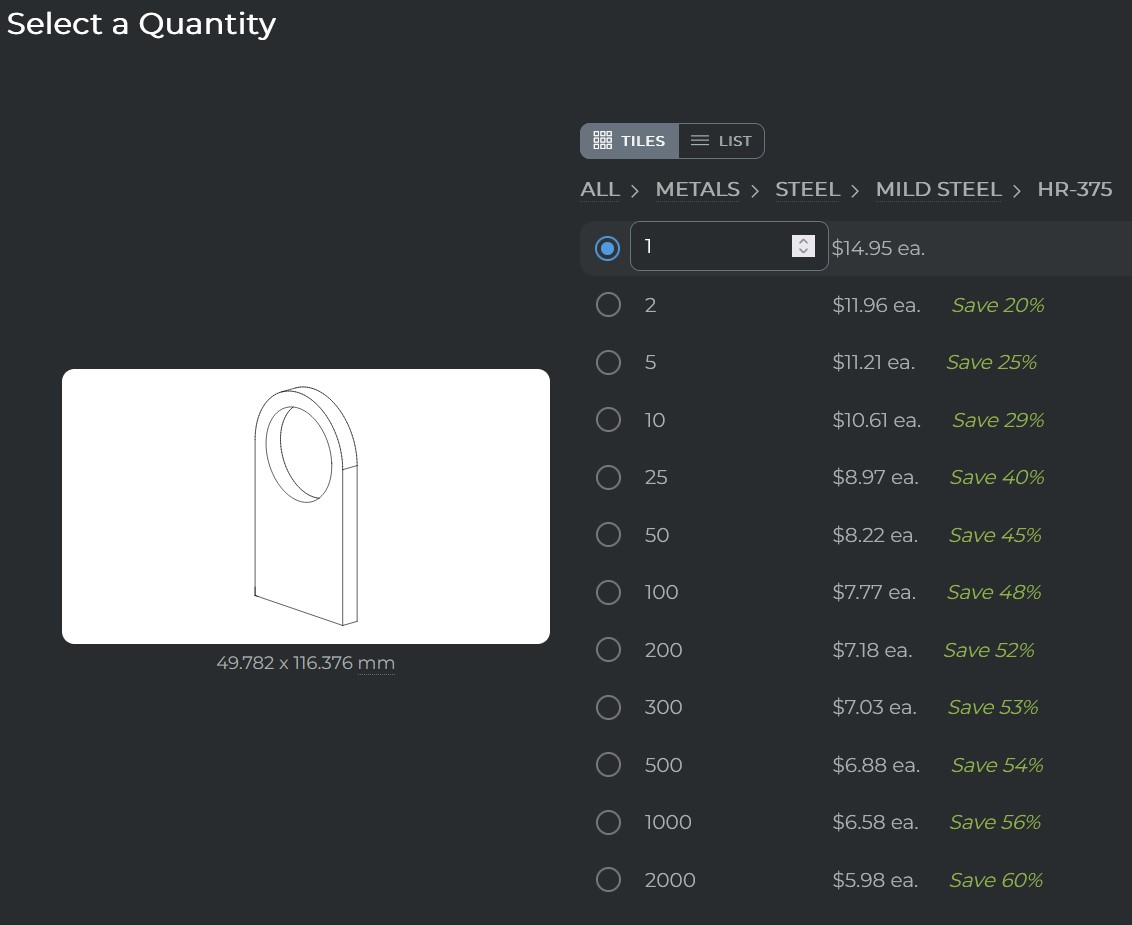
I was wondering if you could get away with pulling off the timing cover (don’t really need it) and using a water jet piece of metal with a bearing pocket welded on using that cover’s bolt points along with maybe the engine mount bolt to make the 3rd bearing. It would put the bearing inside of the output gear and wouldn’t support it quite as well, but probably adequate.
Im liking the crowdsourcing that’s happening here….
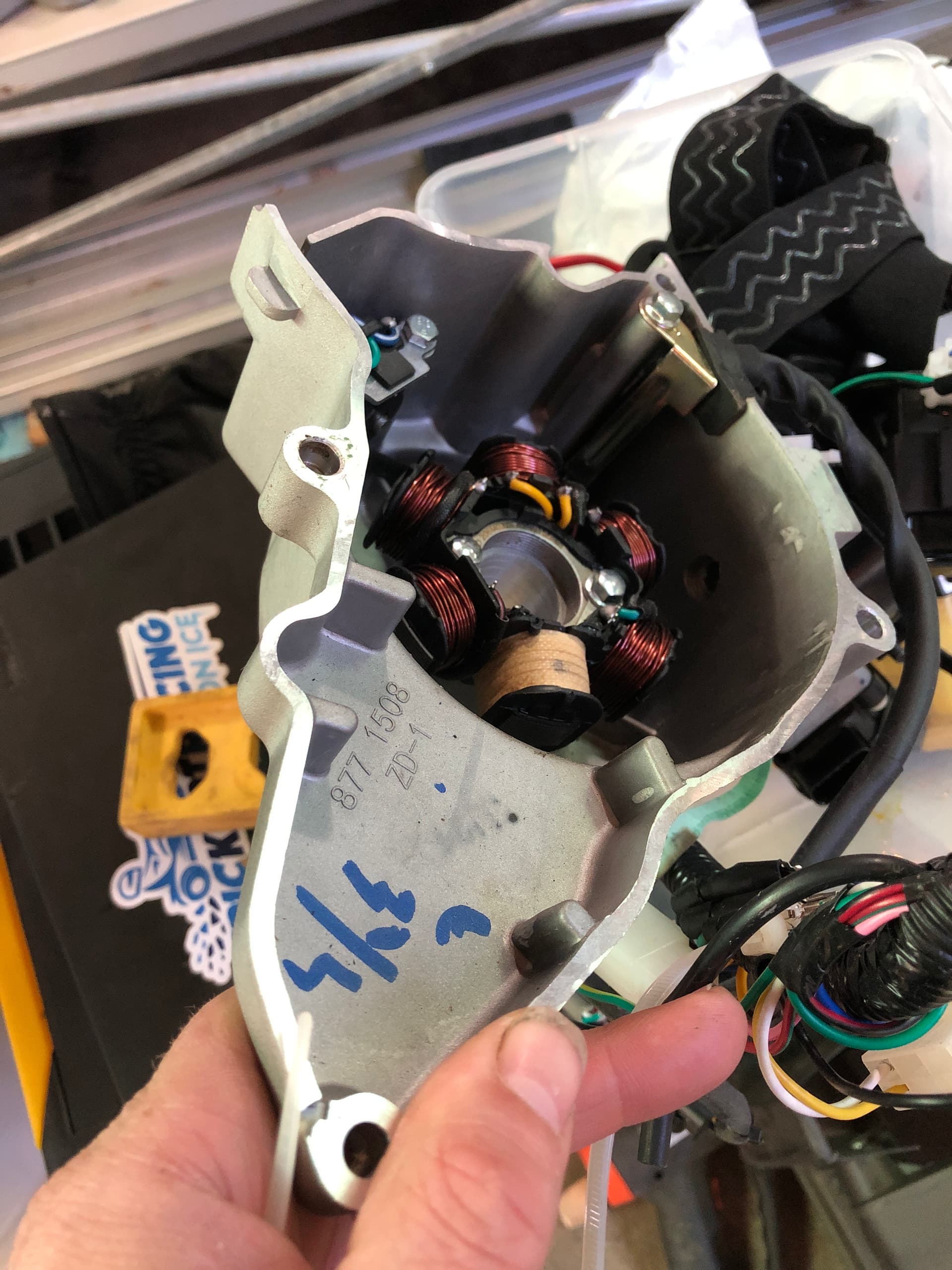
The problem is that the timing cover holds the trigger for the CDI and the charging coil. So a bracket would need to be made that would support both of those in that same location. You’d probably gain 1/2” is my best guess.
Daytona have a setup that uses a stator plate trigger with a different charging coil setup. With this the cover can be dropped, however you lose the ability to use an electric starter motor with that setup from what I can tell. The one way clutch is located behind the flywheel.
Another option is delete the whole system including the flywheel, put a trigger wheel in its place and go with a full loss EFI system.
That said, even after deleting the flywheel, I’m not sure the engine would have enough space to move in as much as we need it to as the next thing to make contact is the seat and cylinder.
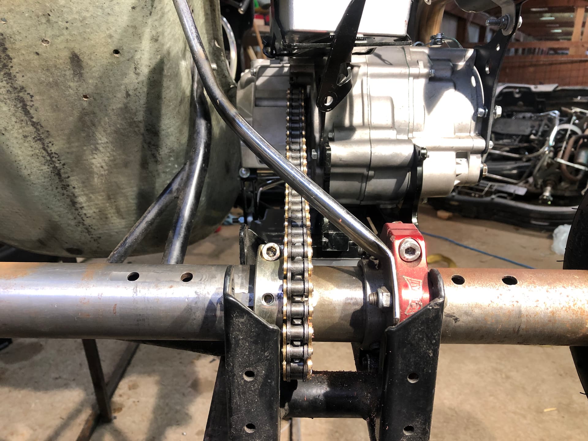
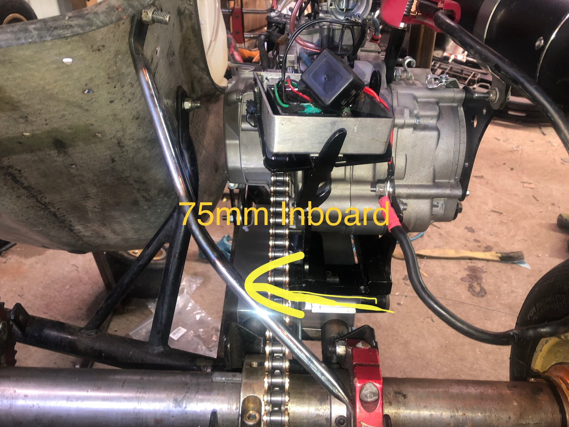
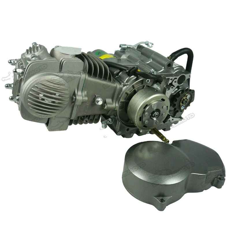
Compared to, say the CR80, the drive sprocket on the Yx/ZS/Daytona engines is quite a bit outboard when compared to the cylinder centerline.
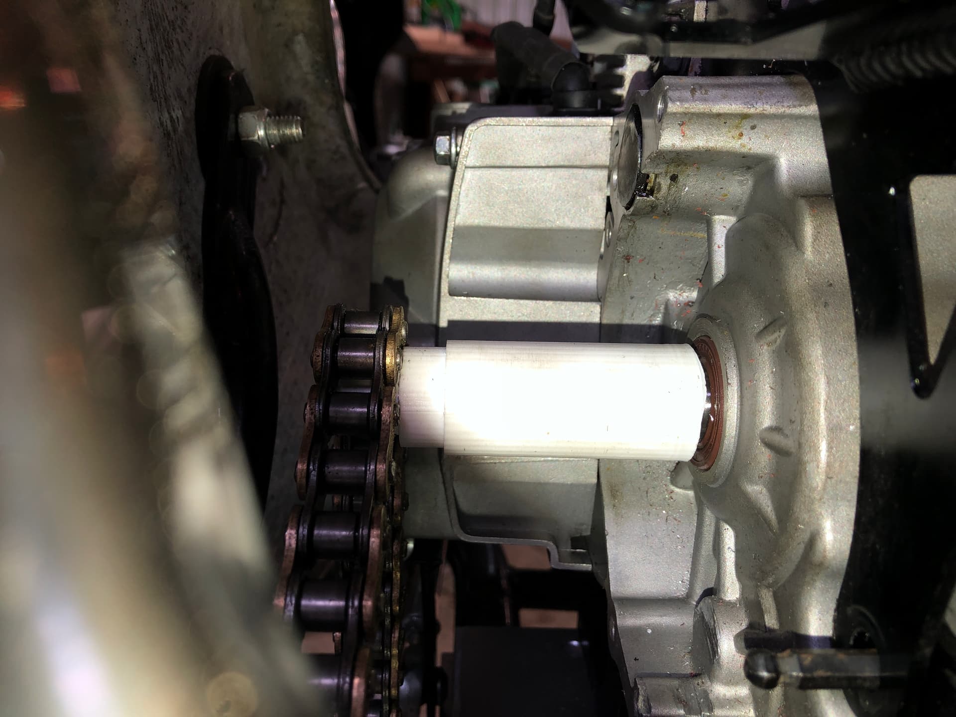
Offset from where rear sprocket is now to where you want it to be. 75mm
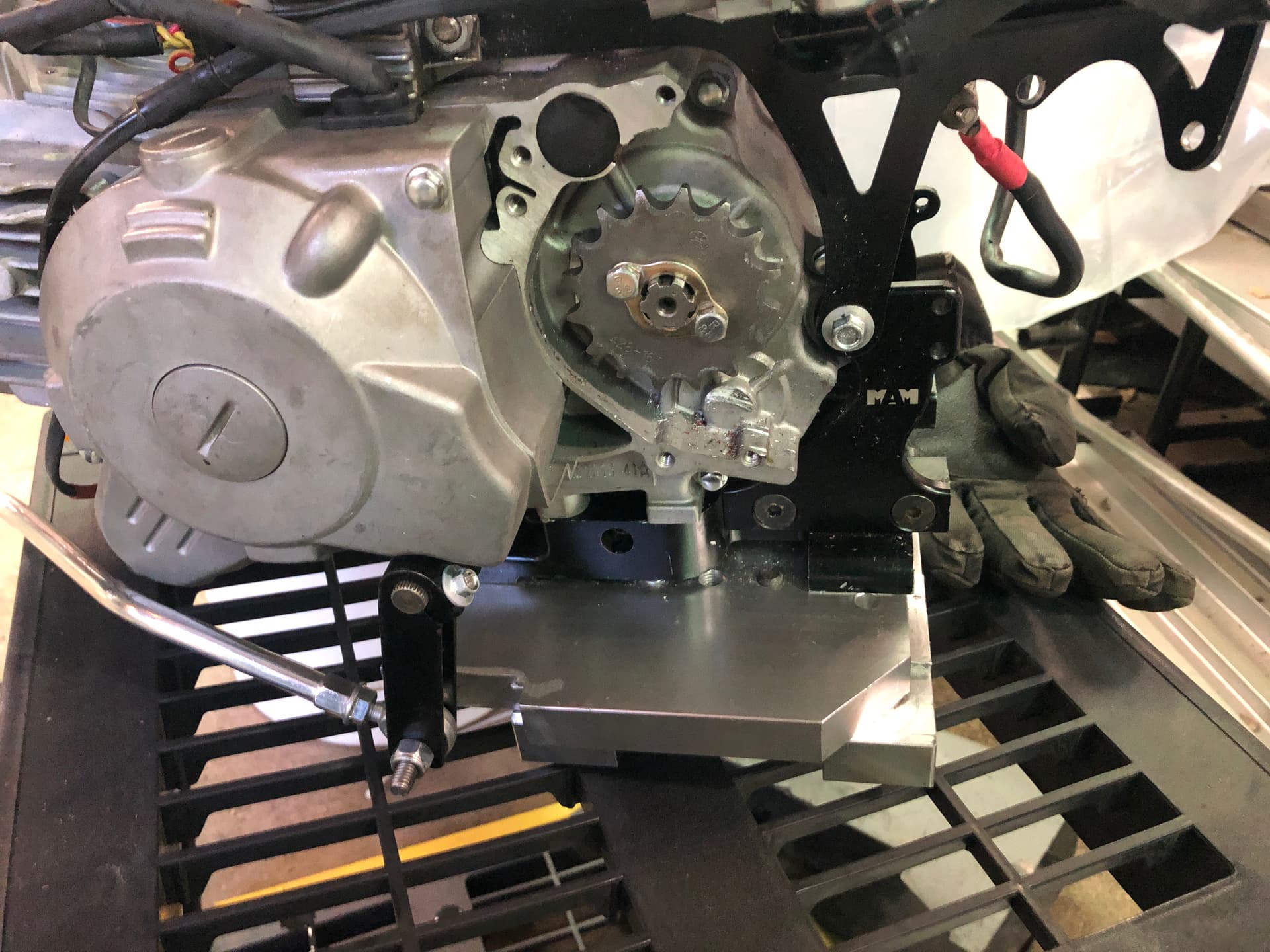
Length of spline cuts before fillet at end.
Not 100% sure what this is but looks like 10mm
Support:
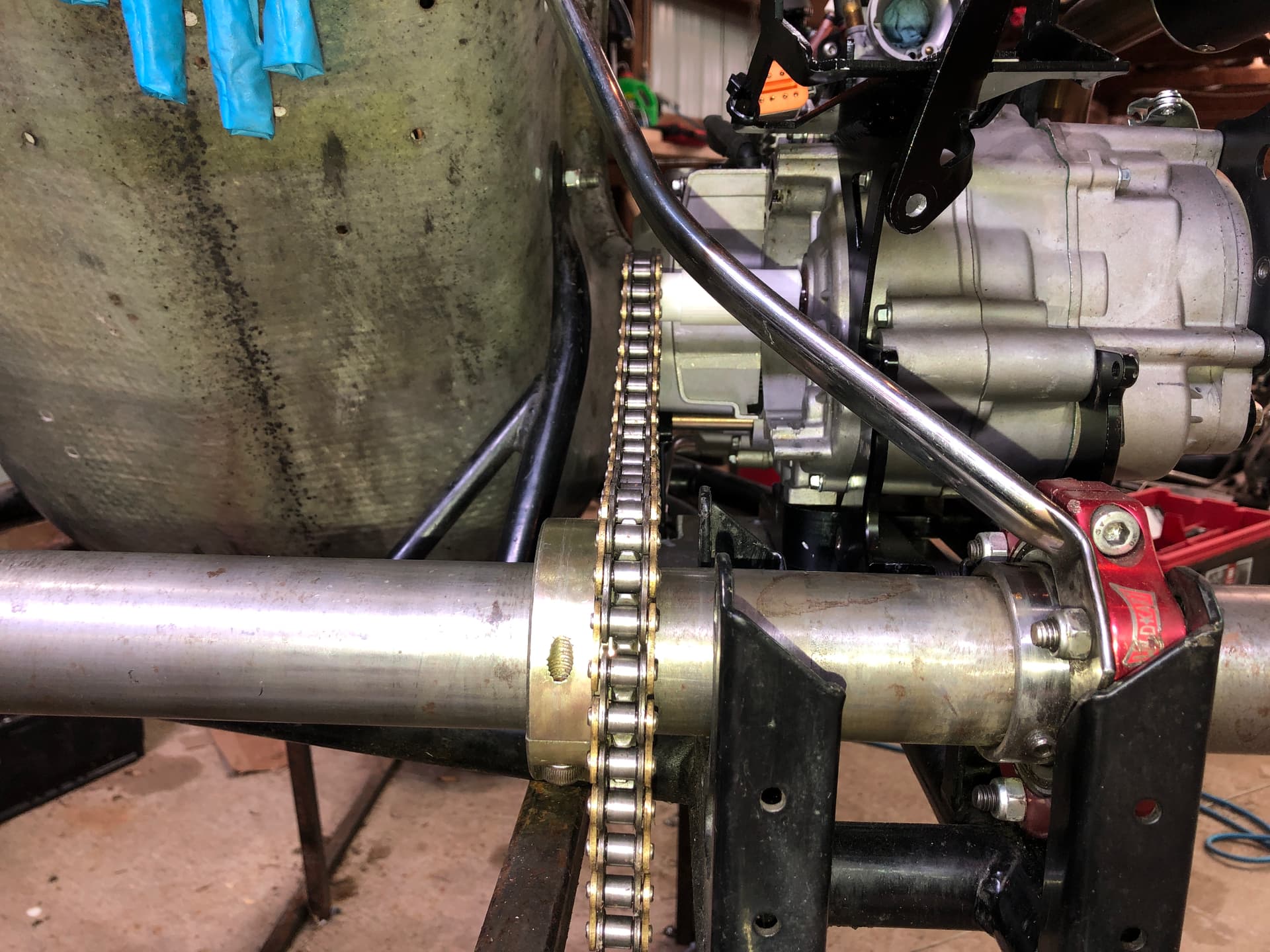
Height from “floor” to center of the shaft. 129mm (so probably 130?) when sitting on black engine bracket which is 35mm. Incidentally I’d like to get rid of the plate and just have the bracket.
Height from “floor” to center of the shaft. 129mm (so probably 130?) when sitting on black engine bracket which is 35mm.
So would that then be 165mm from the bearing center to the bottom of the black bracket?
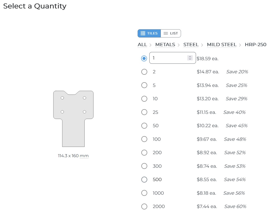
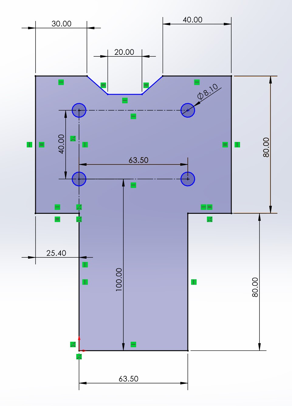
Do you have the dimensions for the plate and holes? I’ll use that for the base of the L bracket so you can get rid of the plate. Also - does it need to be 20mm thick if not aluminum?
Then it would be:
Engine
Black Engine Mount
L Braket Base
Kart Frame
Frame Clamps
This is what I currently have for the base for reference:
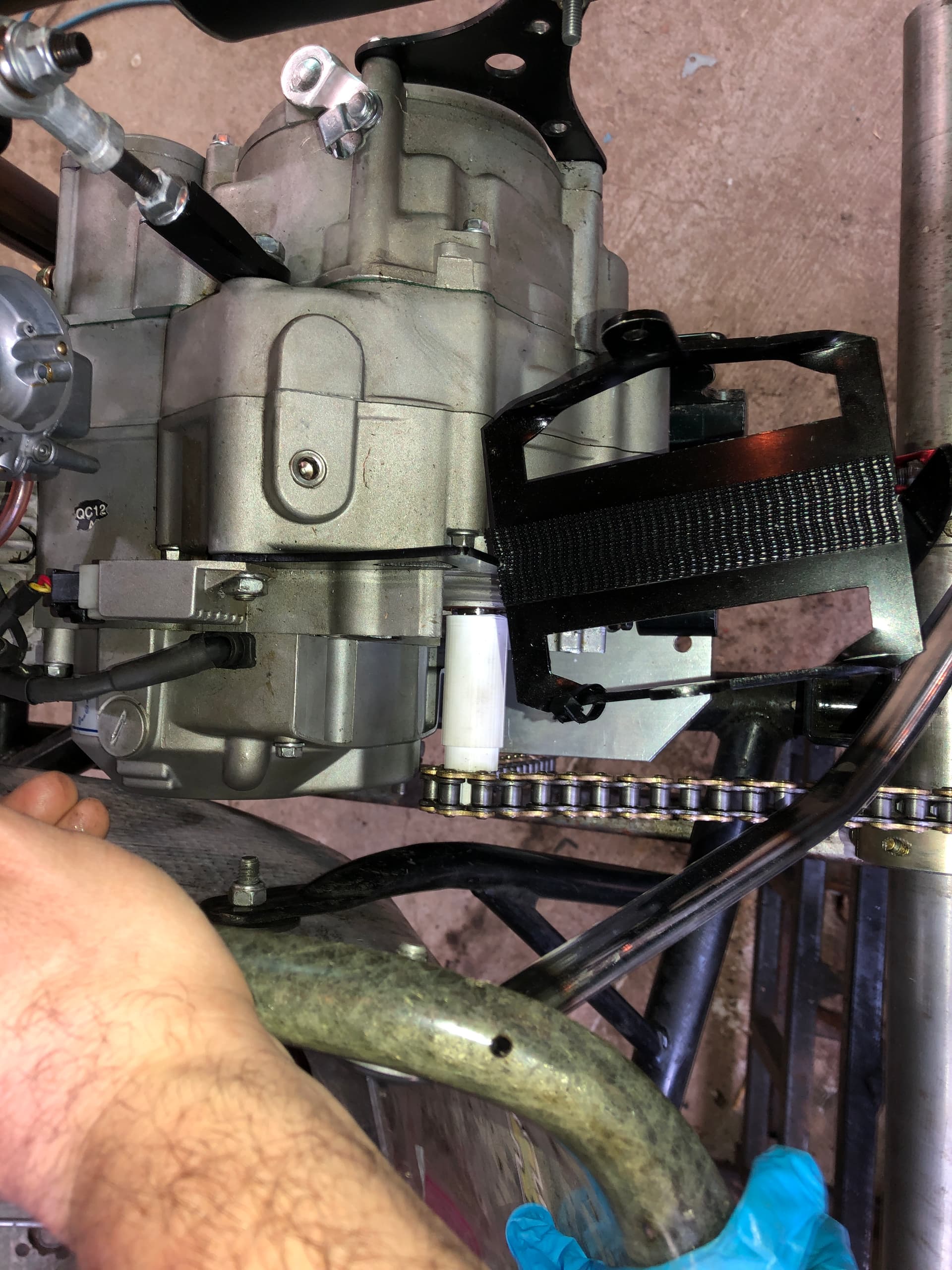
Boy that engine mount is quite the monstrosity. Seems unnecessarily tall. I would think the entire engine could be dropped a good 30-40mm with a different mount. With moving it down you could possibly be able to move it to the left some to shorten the extension needed. I know a guy that builds custom engine mounts for a lot of dirt race karts that could probably build something with a third bearing all in one mount.
For sure it’s massive, more or less a prototype. Overly tall and like you say, we could get a couple mm inboard by dropping the motor down some. Definitely interested in talking with people who can make these at a future time.
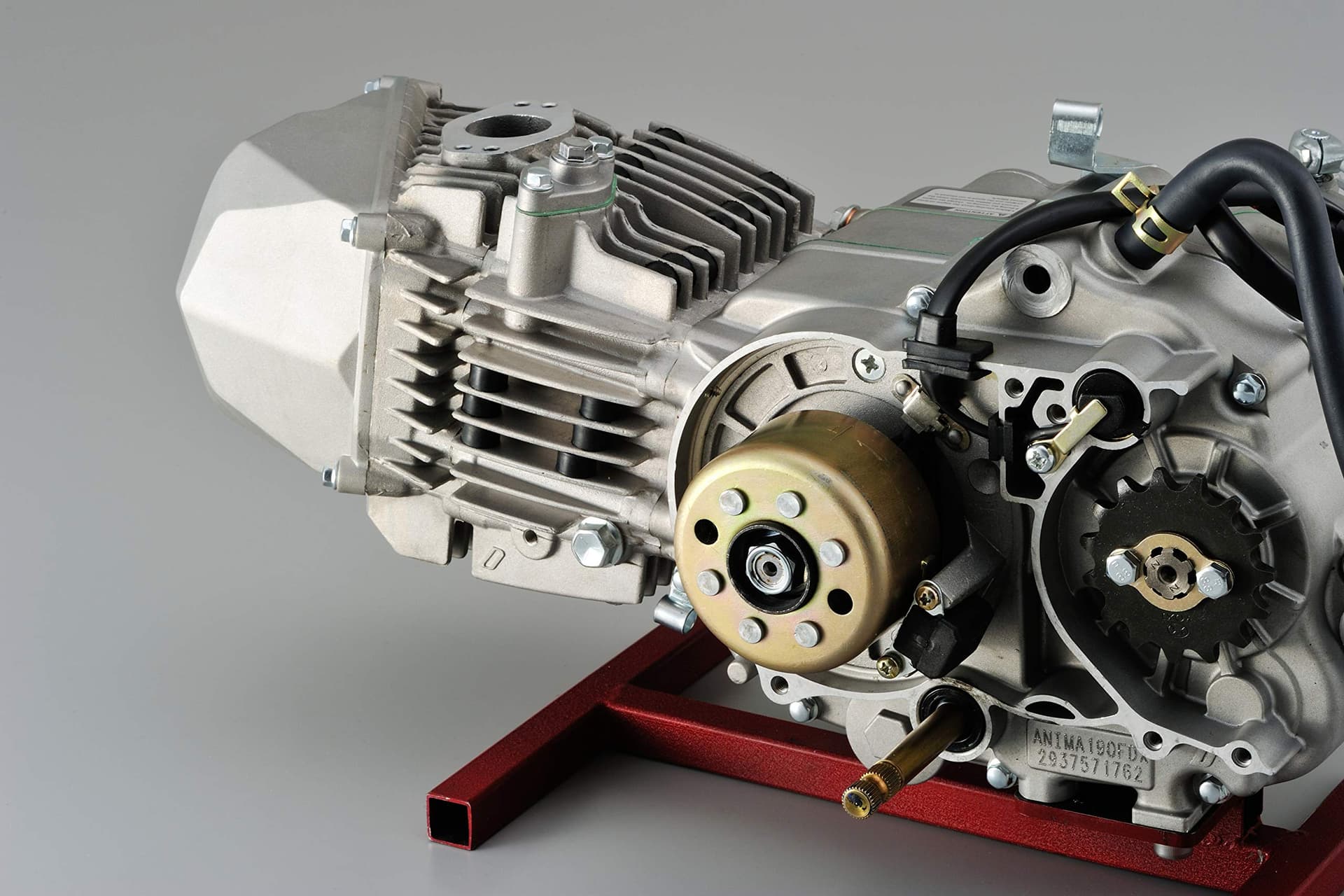
It’s interesting that specific model has the stator in the cover, whereas looking at a standard yx150 and daytona 190 have the stator inboard mounted to the case and the rotor outboard. In which case the timing cover could be left off to shave off some width.
Yep those are the non electric start ones. The anima Daytona electric start has the same charging coil on cover setup.
The racer in me much prefers that style you have, plus it’s easier to tech the trigger advance.
But the “product manager” is pretty adamant about having an electric start.
I guess a bracket could be made to support the charging coil. Designed in some way to be more space efficient. Worth noting the rotor on the electric start models is pushed out by having the starter clutch behind it.
Or could go with a full loss battery powered system and forget the charging coil altogether. In a way I like that because it’s one less part to fail or troubleshoot. Also given it uses power from the engine, arguably it could be an area of “tuning”.
As long as the ignition system is self sustaining (not a total loss electronic ignition) then I think having the starter system be total loss would be fine. Keep a trickle charger on it, and you’re good (like most of the tag engines).
It’s arguably a safety thing too. Driver stalls on the grid, or on the track they can move on quickly.
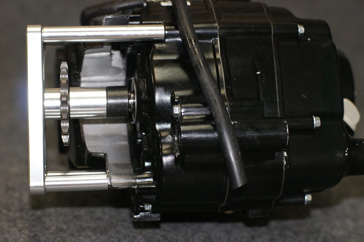
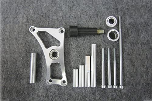
I (re)found products for the Honda engines for output shaft extension. It doesnt looks like you actually get one anymore however, and I think the case bolt pattern is different in the clones.
It offers an offset of 48.5mm or 18.5, presumably by way of two spacers that can be swapped.
Nonetheless, interesting to reference. How well this would hold up under the jolting of a racing kart, I’m not sure.