I need an output shaft extension designed for my pit bike engine project and figured it would be cool to have someone on the forums do it. In stock form the drive sprocket aligns with the area between the two right bearing carriers and that’s not acceptable to me for safety reasons, requires holes to be drilled in the axle for a new key way and the area lacks the reinforcement that’s present on kart axles with a traditional inboard drive for shifters, 206 etc.
Shaft will go onto the existing male spline and extend
It about 3”. The extension will need a support of course so we might add that as part of the design.
I can take some 3D scans, measurements etc or whatnot as needed
Let me know if you’re up for it!
/Edit I should state that the plan for this is to be a commercially available product.
Depending on the spline type fitment can be tricky. I found that making a part in CAD (I am using solidworks maker) and then having it 3D printed to ensure the overall design and fitment is correct is a good ideal. The 3D tolerances aren’t what machining will give, but they are good enough for most things. I’m not sure about the ID smoothness of the tube where it would need to go over the shaft. I could mock up something if someone will give machining input on tolerance values for this shaft for the final CNC’d part.
That’s kinda what I’m thinking is to use 3D printing for mock ups at least. I’m sure when it gets to full-on production I’ll need to consider metallurgy too.
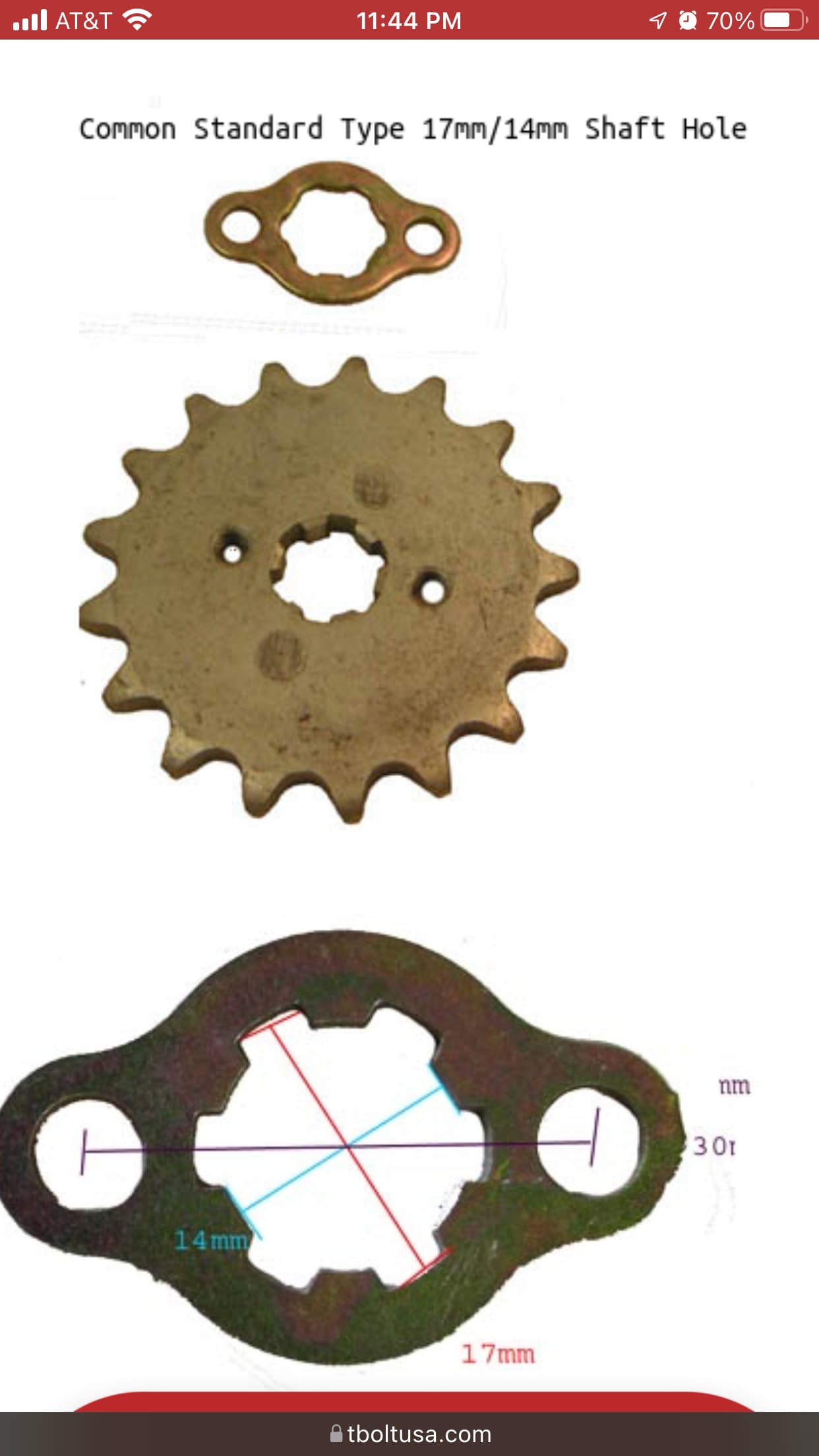
I’m not sure where I can help on tolerance values, but here’s the dimensions of the spline pattern.
I’d also need to know how deep the flange cuts are, how deep it can go over the current shaft, as well as how long the shaft extension needs to be overall.
I’ll work up something tonight for visualization purposes.
I have a sense of what you need and will try to get it this weekend. I have a spare transmission at the house, but no calipers. All the good stuff is at the track
Is the primary drive shaft going to be up to the increased strain induced by adding an extension to it? Will the (bolt on?) extension be able to handle that as well?
I’ve been summoned?
I’ve gotta finish Bryan’s motorcase first (on spring break but should be done before may), but if I finish before I graduate I might be able to eke it out.
Due to… unpredictable circumstances at school, I’ve got a lot less time with the machines than I’d like, so things are taking a while.
I could also see if I could get a model printed at my job, we do super high precision 3D printing
Just curious what engine you’re using and whether it can be moved to the left so you don’t have to use an extension. I know Odenthal has made a mount for the Daytona 190cc engine that Musgrave has been utilizing.
I thought that Musgrave had a different mount to odenthal.
It’s not possible to move it inboard far enough because the drive sprocket is off set outboard from the magneto by about 2 inches. In other words with the engine against the seat, the drive sprocket is lined up between the two bearing carriers. You could claim some space back with some work on the flywheel/charging coil setup but not enough.
I have several that im testing. Yx, ZS etc. All the same CRF50 form factor.
When I talked to odenthal about the mount it sounded like it was priced as more as a premium product and not really a good fit for the goals I have for this project. At the time it seemed Iike it was still driving an non reinforced portion of the axle too.
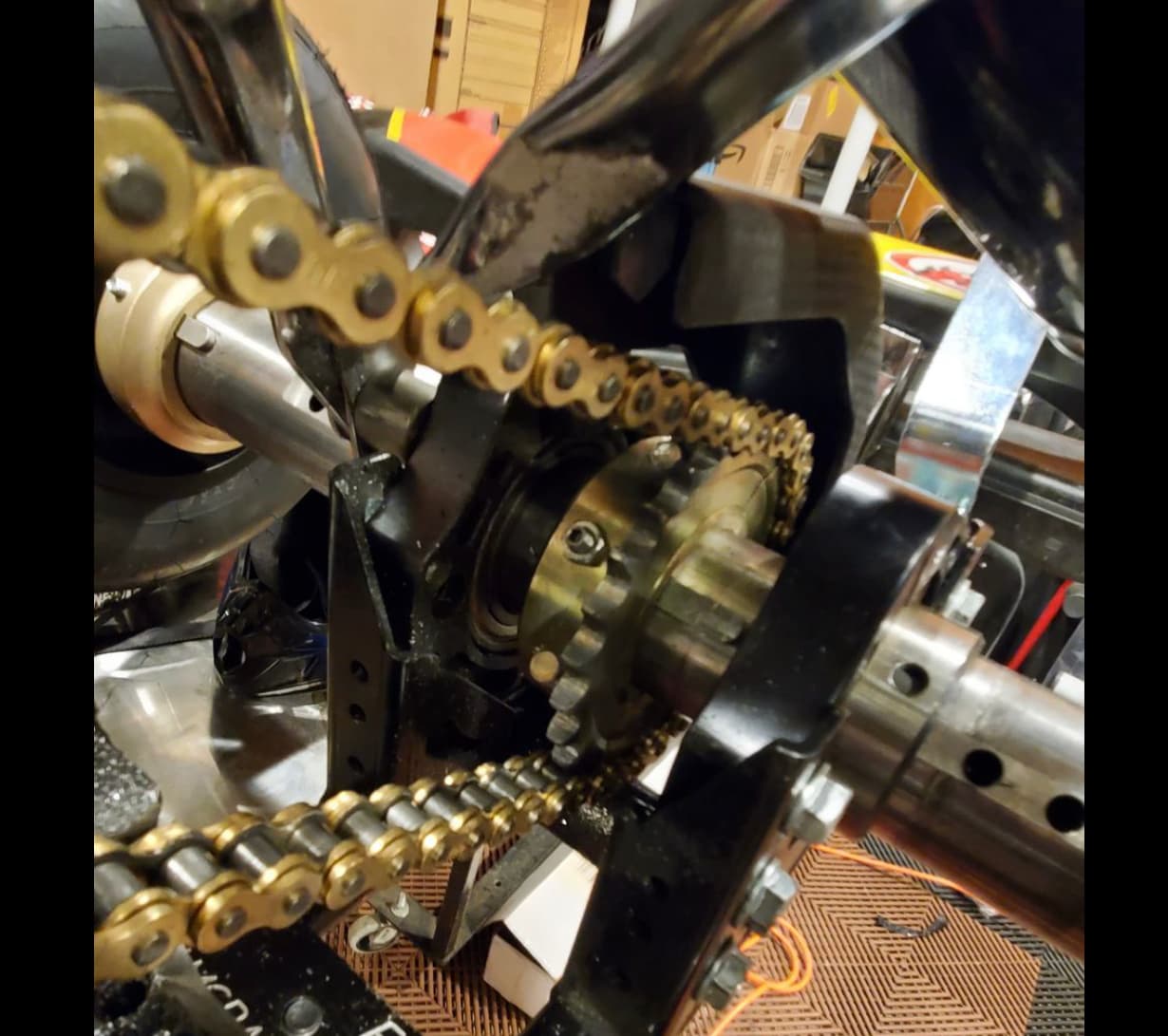
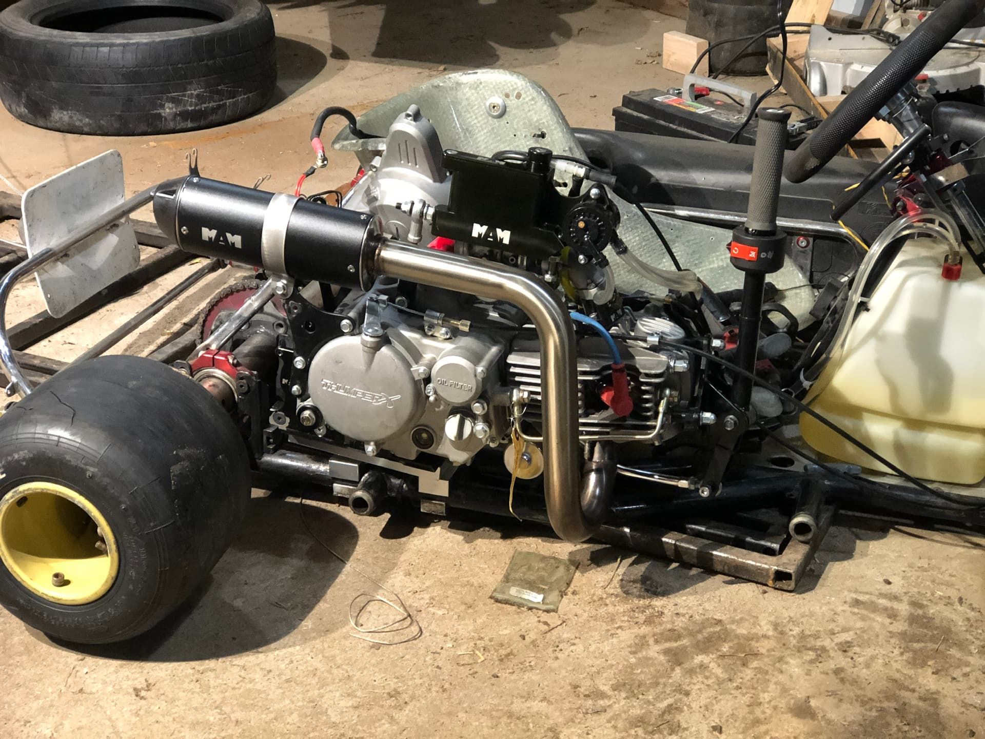
Here’s a pic of what’s currently on the chassis. It’s already driving the axle between the bearing carriers, but it’s really not something I believe should be a practice.
Yeah, I just had to look back at the trackmagic they setup with the 190 and it also is driving the axle between the bearing carriers. I wouldn’t think that would be a big deal other than having to make the new spot for a keyway. You could use one of these axle reinforcements righetti makes. https://righettiridolfi.com/en/product/search/axles/reinforcement-for-axles
I think the image of the sprocket I posted might be from Jason Lapoint’s actually. There’s something about people having to drill their axles that just makes me uncomfortable.
Thanks for that product link, didn’t realize that was thing (or maybe I’d forgotten). Problem is that by requiring a keyway to be drilled means that the package can’t deliver on the promise of being a “bolt on and bang gears” experience.
Indeed, but you’re willing, capable and interested in doing that kind of work. The kind of person that this is intended for has no interest in that what so ever.
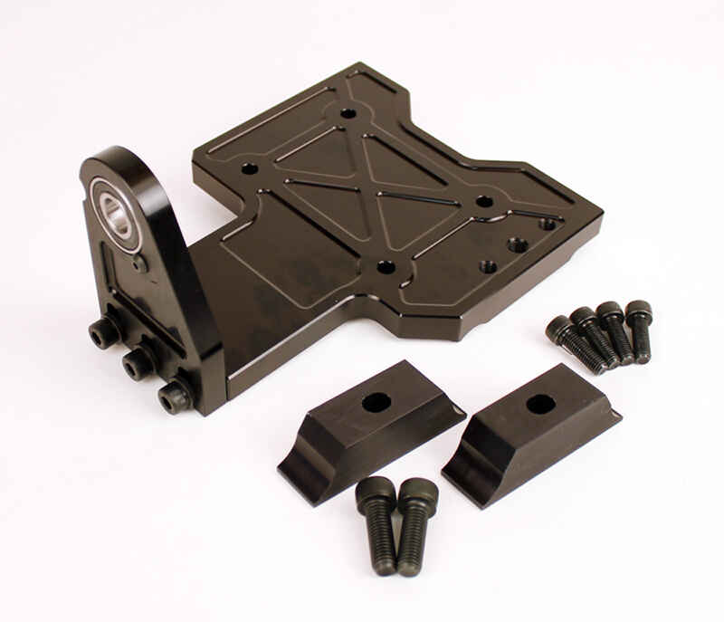
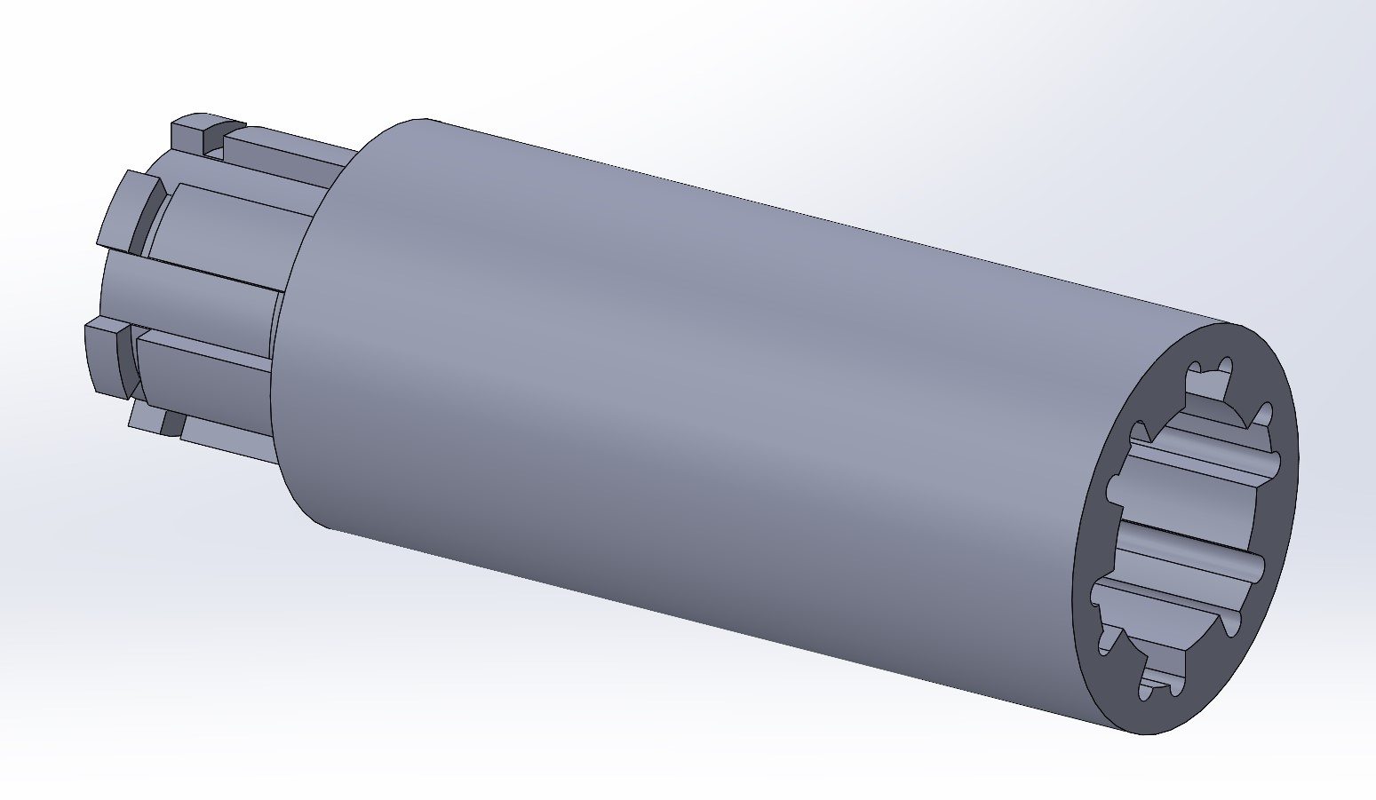
Something like this?
Not sure on depth of the sprocket, or how far the cut needs to extend to go over the shaft. It will also need some way to anchor it to the existing shaft, possibly a flat with a set screw. Overall length is also a guess.