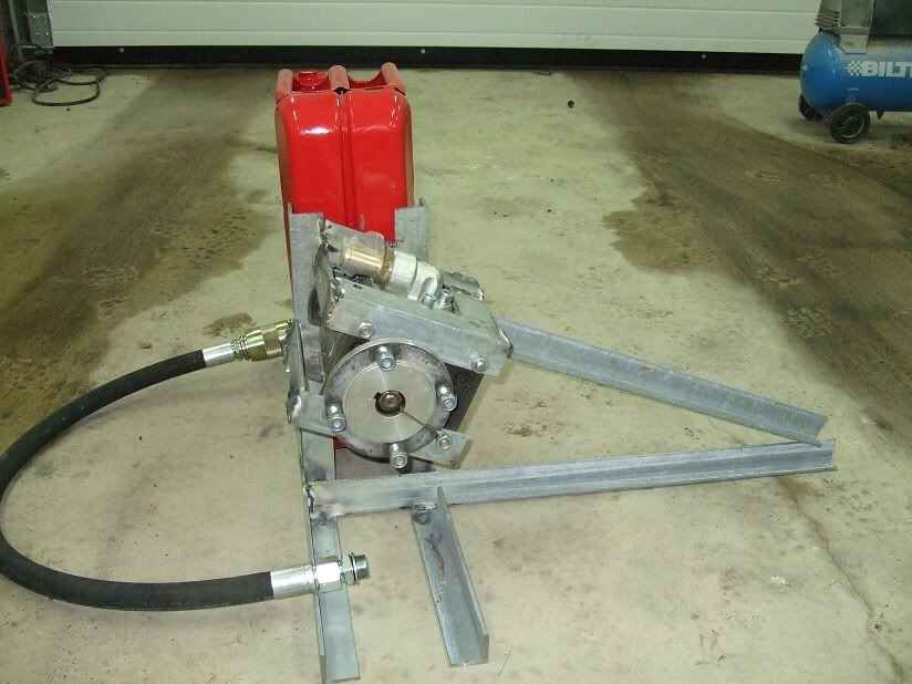
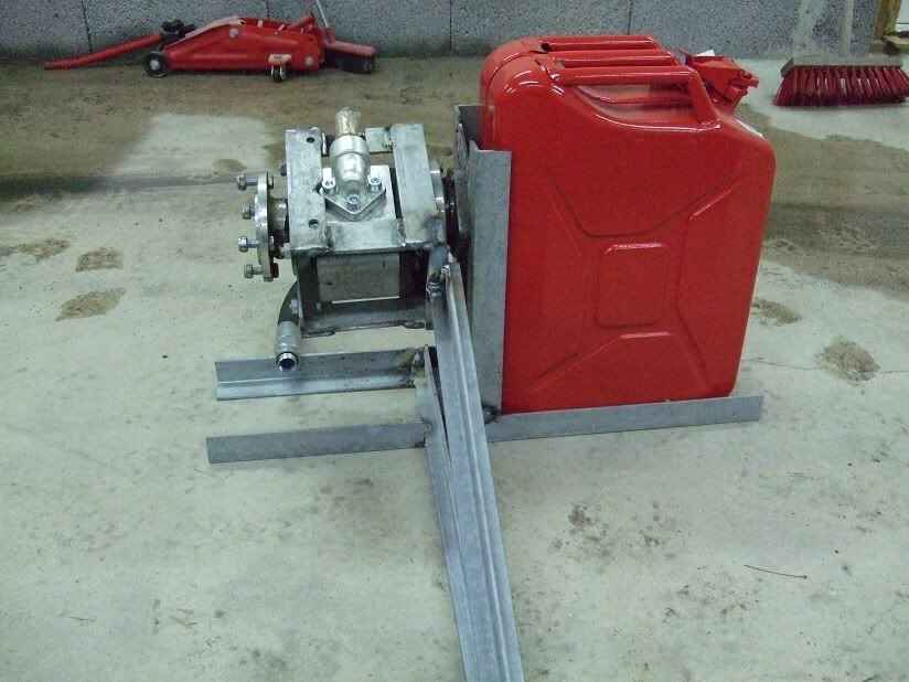
Pretty good chance I’ll build one of these this year for fun.
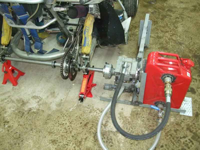
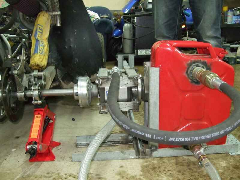
I really like idea of being able to remove a rear wheel, mount the pump unit on the hub/axle and do some runs. A good way to test all the rental karts
Ideally I’d like to have a dyno/pump controller too for ramp/steady state testing and use a load cell that measure torque/force vs working it out via flow and pressure readings.
Finding a pump that will load the way I want it to at around 1800 RPM. (Axle speed at about 60MPH)
You can compensate by raising the pressure… but 4000psi makes me leery
Electric hydraulic control. There are controllers out there starting at $1000, but for our needs that would be like using a sledge to swat a mosquito. I’m poking around in Speeduino and Ardunio communities to see how I can build a controller for the pump.
I think I could use the idle control circuit that’s on the Speeduino board to control a hydraulic valve, I also need to find out what that valve should be.
Software needs to be tackled too, but that’s another battle.
There could be a marketable solution here IMO. Again the single cylinder/small engine segment has been kinda overlooked with this.
You could just spin the axle, but that would be a super short run. Even a 206 will spin the axle in (guessing) two seconds.
Plus I need ability to do static loading, holding the engine at certain loads and RPM to dial in AFR/jetting and ignition timing.
I’ve seen enduro guys make a set of small rollers to put a bit of a load on the engine to help with breaking in. No measurement, just some rollers 1” diameter or so that spinning them slows the acceleration of the axle some.
So, just spit balling here. What if you did a counter weighted disc, but instead of a direct drive, you over-geared it to produce a steady load. To make it simple, you have your standard driver sprocket and standard driven sprocket on the the axel, but you add a calculated large sprocket to the axle driving a smaller driven sprocket on a weighted disc. This way you can compound the forces with a smaller weighted disc. It remains a simple jig and you can easily calculate power without all of the hydrodynamics of a pump. The weight acts as resistance like a pump, but you don’t have the bulky tank and a proportioning valve to deal with.
Exactly, but the only way to create a load variable cell is to use an electric motor that can adjust the current. What the guy in the video did was to create a hydraulic pump that induced a load. It did not increase with rpm, but rather gave a reference. Why not use an inertial load and gear it down so that it does not require a huge spinning disc? If you want to vary the load at higher RPM you could add spring loaded counter weights that would increase the diameter of the spinning mass to increase the load as it increases RPM. By tuning the springs and the masses, you could maintain a relatively steady load as the RPMs increase. Granted, it would take some R&D, but once tweaked for a given range, I would be easy to adjust.
The goal is to have something that can quickly be put on a kart without too much adjustment. Literally unbolt the left rear wheel, attach the pump assembly to the hub or axle and start doing the runs.
The electric motor and hydraulic pump setup can do the same thing as far as I understand. I could be missing something. Load can be modulated as needed for the desired RPM, but that load is not linear across the RPM range of course.
I’m kinda psychologically invested in and committed to a hydro setup at this point, not needing an electrical source is a nice bonus.
Longer term I would like to have an intertia setup to compliment the braked one though.
But for now I’ll try to get to the metal place, get some tubing and start making highly questionable welds.
Neat idea and I see that there has been some prototyping done. In a load dyno, there has to be somewhere for energy/heat to go. If the tests are short and far between the need for a heat exchanger to cool the oil might be avoided. Get someone to calculate the heat load so that you won’t end up with an investment that won’t be practical. Don’t forget to cool the engine.
The inertia dyno doesn’t build heat but is somewhat scary because of the rotating mass. I think the flywheel has to be relatively heavy to keep the RPM down but the inertia dyno allows you to run up the RPM curve rather than down the RPM curve, which is a better representation of real conditions. There have been some hybrid dynos that have used an air pump to represent the aerodynamic load, in combination with a flywheel to represent the mass of the kart.
You might want to find a engine builder who uses a load dyno and one who uses an inertial dyno and see their setup, even for a small engine there is a lot.
For an electric dyno a power “sink” is needed not a power “source”.
The “sink” would be somewhere to dump the energy maybe across some large resistor banks with fans or batteries. Could the batteries be used to power the cooling fans for the motor?
I problem I see with an acceleration dyno, at least the ones I’ve seen, no peak load device. Yes, that wheel resists acceleration, But when acceleration slows, the mass of the wheel is a feedback to the engine.
That’s part of the problem, there’s one person I know with a kart dyno around here (Noah Stark at NSEW) and he’s pretty busy. Probably worth noting that I’m not nessacarily looking for engine builder type results, at least not at the outset.
Inertia type is off the cards from a portability standpoint, even for a small engine it takes a pretty big mass and those seem to run $1000 alone + fabrication of the dyno frame etc.
You can run up and down the RPM range with the hydraulic dyno, but you need a means to control it electronically. That’s the main thing I’m trying to figure out right now… what components do I need for such a controller system.
Heat is a big factor of course, but I’m going to cross that bridge as I come to it and add extra cooling as needed (Engine and dyno)
OK that makes sense. Battery power is always doable. I’m resisting the urge to research using motors (or load cells) for now.
I thought about this last night. I would think that picking up a few alternators at a pull-a-part and then loading them down with either resistive heaters or large filament lights would be the least expensive way to go. A used single or 3-phase AC motor could also work well.
Either should allow you to adjust and provide a constant load for as long as you want, as apposed to most of the inertia dynos you find.
I had dyno, water break, in 1985. It was a Go Power unit. It had an electronic strain gauge for torque readings and an electronic RPM gauge. RPM control was through a custom-made manually controlled water valve. I had digital RPM and EGT gauges at the control station, an analog/digital converter and a computer with custom-made software. I built my own stand. Cooling, for the engine, was just a fan. Barrel cage type. The airspeed was tested at about 40 miles an hour.
Pretty cool idea. I though about building a dyno earlier this year, my idea was just simple rolling road, tire to tire on a platform. A kart brake with a servo to control the speed and load cell to measure the force, everything can be controlled with a Arduino. The main concern of my idea is about consistence.
You might be able to use a high torque servo to control a mechnical flow control valve to regulate the pressure.
Yeah that’s come up too. PWM valve or a servo of some sort. It’s hard to know what will work without trying stuff it seems. I feel like the PWM solenoids might have a fairly peaky range.
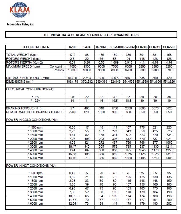
In other news, curiosity got the better of me and I asked about eddy brakes. Doesn’t look like they would be practical for this “luggable”, axle mounted kind of project.
Here’s a chart… Looks like in an axle mount situation (RPM of 1800 at 60MPH) we’r elooking at a big lump of at least 88Kg (193LB) for the eddy brake alone going with the K-40C.
The K-10 would work nice with lower HP engines like 206, Tillotson 212, clones etc. though.