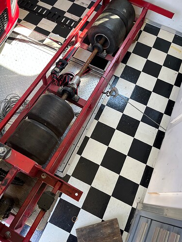
Thought I’d toss in a bit of my very early experience on inertia dynos (keep in mind that was 1978, but I believe a lot still holds true):
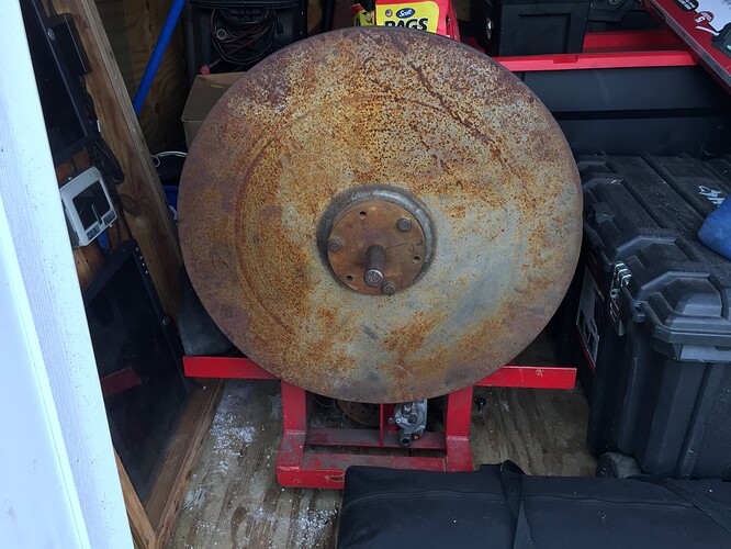
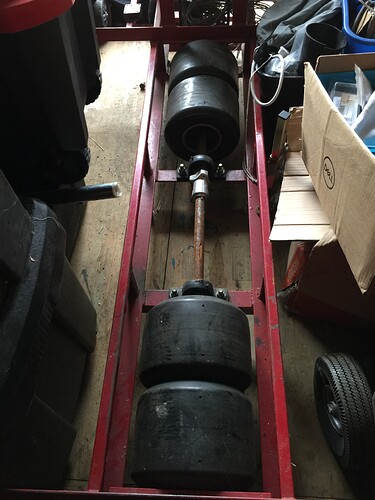
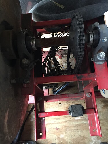
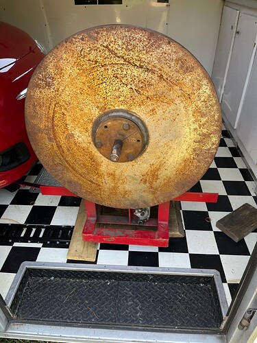
The first dyno I was involved in was designed and built by Doug Henline (yes: Proline / Douglas Wheel /etc). Brilliant design, IMO. The flywheel was around 550 pounds… maybe 2’ in diameter and 4" or 5" wide. It was belt driven by an intermediate shaft that was the same size as the kart axle size of those days (1"). There was a “typical” motor mount on the dyno, which allowed running pretty much any type of engine from that era (McCulloch, Italian engine, whatever). The beauty of the system was that you could also install the clutch (and test it) whether it was engine or axle clutch. Oh… Doug also mounted a big caliper to the dyno frame and added a disc brake rotor to the flywheel. As I recall, these were both off a Cadillac Eldorado from the wrecking yard. This allowed slowing the flywheel down pretty quickly so you could do another run!
sidenote: (If you put a big brake on your flywheel to slow it down quickly, don’t forget to bolt the dyno to the floor! Otherwise… a big handful of brake and you could flip your dyno over!).
Additionally, the intermediate shaft also drove a GMC 4-71 blower, and the intake side of that blower had an adjustable valve (more like a “shutter”) so you could change how much air was going into the blower and consequently the load the blower was applying. The output of that blower blew onto the engine for cooling (proportional to the speed, which was ideal).
Initially, we were “mostly” using the dyno for enduro racing setups (aka: “road racing” now). The initial “setup” of the dyno was pretty simple – a couple of people just hit the track and timed themselves through the rev range (e.g. standing start to clutch engagement, then time how long it took to get to each even thousand rpm, and note where peak revs were on the track). Armed with that data, the exact/entire package (clutch and all) was taken off the kart and installed on the dyno. With a few iterations of changing the gear ratio from the intermediate shaft to the flywheel, and messing with the intake on the blower, it was very close. The engine would accelerate at the same rate it did on the track, and the blower would increasingly apply more drag (just like aero drag on the track) until the engine “peaked out” just like on the track. It was fine-tuned slightly over the next couple of months as I recall, and we also added a strip-chart recorder (yes… old school, no PCs back then), and the strip chart read the pressure from a small hydraulic cylinder that was under the leading edge of the motor mount (which had a pivot on the opposite end, so the motor mount could just slightly move). Essentially, this provided a “torque” reading through the rev range. There was, of course, a bit of “tweaking” required if you wanted to simulate a heavier or lighter “kart/driver package”, but that usually just required a small gear change intermediate shaft to flywheel.
We had a tach on the engine of course, so someone would just watch the tach and place a little “tick mark” with a pencil on the strip chart paper at each 1000 revs. The key “tools” when using the dyno was simply a tach and a stopwatch. Since the strip chart runs at a fixed speed… it already has “time” marks on it, so you could also go back to a saved strip chart, and see how long it took from 11,000-12,000, 12,000-13,000, or whatever you wanted.
The real genius behind the system was that once the gearing and load were tuned in to being very close to what happened on track, it was possible to pretty much swap engines (complete setups, really) onto the dyno and every setup pretty much “acted” (and sounded) just like it did on the track.
When Doug designed the dyno, I believe his primary concern was to make the flywheel “big enough” for the highest HP and slowest accelerating setup. In other words, if the flywheel has too little inertia, then it would be necessary to “gear it up” to spin faster, which at some point becomes dangerous just due to limitations in the mechanical properties of the flywheel material. If the flywheel is “plenty” heavy, the only consequence is that it had to be “geared down” from the intermediate shaft to the flywheel. Easy and safe. The same amount of stored energy is still in the flywheel, but a heavier one (one with more moment) will be spinning slower.
Clutch development on this dyno was incredibly easy and productive. The entire drivetrain simply “acted” like it did on the track.
This dyno design was so successful that it was copied by many people around the country. If I was building a dyno today, I’d be inclined to build something very similar, (with a computer-driven data acquisition package on it). Of the many dynos I’ve been around in the last 40 years (ugh!), that original one that Doug designed is still the only one where the tuning, sound and feel of the engine was exactly like it was on the track. Yes… it can all be done with a computer-controlled pump or eddy-current load these days, but something about accelerating a “mass” that has been geared to have the same inertia as kart you’re trying to accelerate is just… well… better (in my opinion). The blower for limiting peak revs and providing cooling air was great too, as it “acted” pretty much like the airflow the engine felt on-track. It pretty much sounds like a good number of you already have inertia dynos, which I think is great! I thought I’d just toss out the info on what I think was the first “serious effort” at a very well-designed and functioning inertia dyno.
