Last night i was reading this story , and i couldn’t stop my self from make the question .
Any news from the dyno project ?
Goodmorning from greece .
Last night i was reading this story , and i couldn’t stop my self from make the question .
Any news from the dyno project ?
Goodmorning from greece .
Not a lot to report yet, but I suspect we’ll have more progress this summer.
Summertime update while I have a break from work. Hoping to get each of our rental karts on it for a baseline before I send the motors out for a refresh. Then will use it to baseline the EFI setup on the 4T shifter.
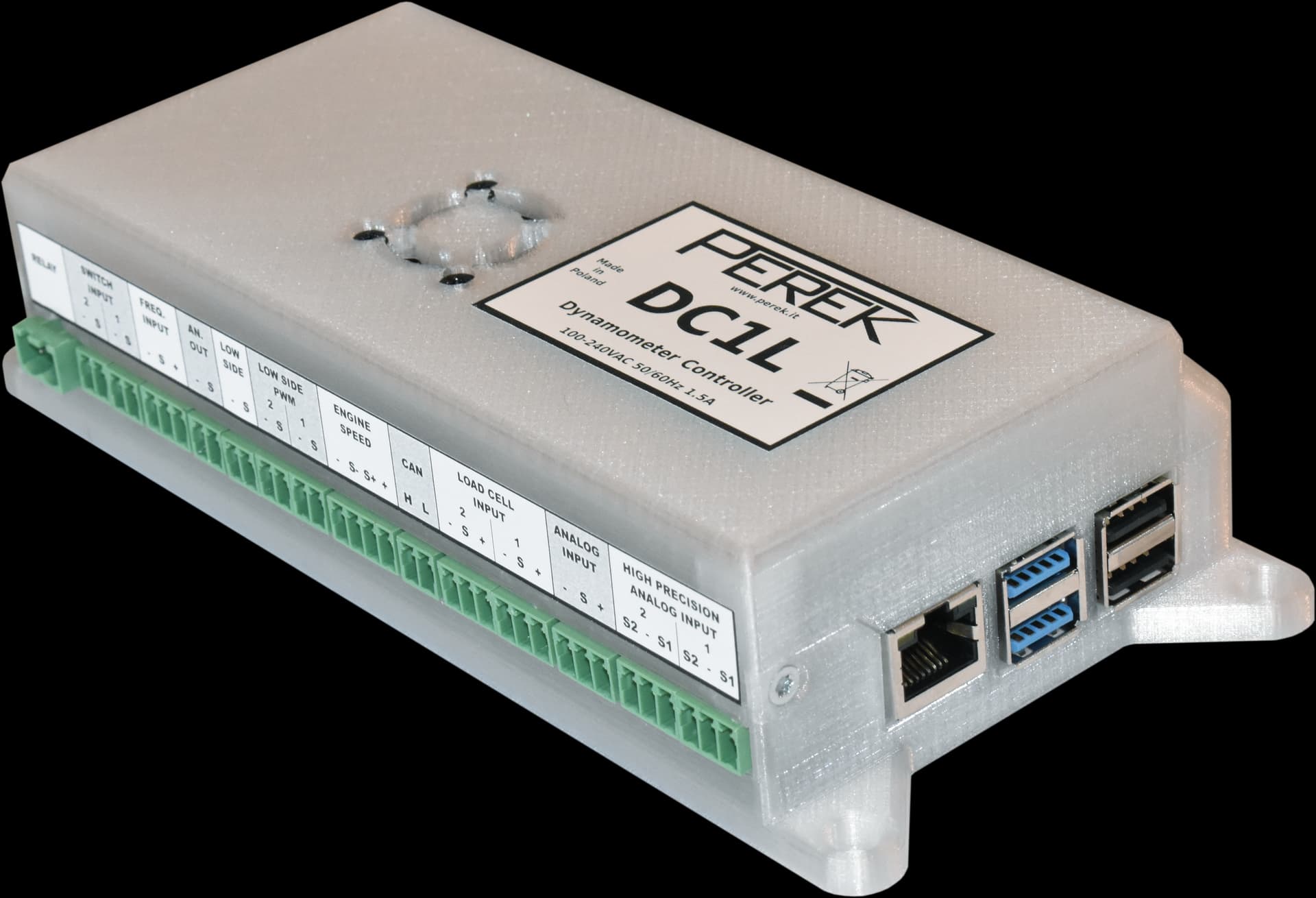
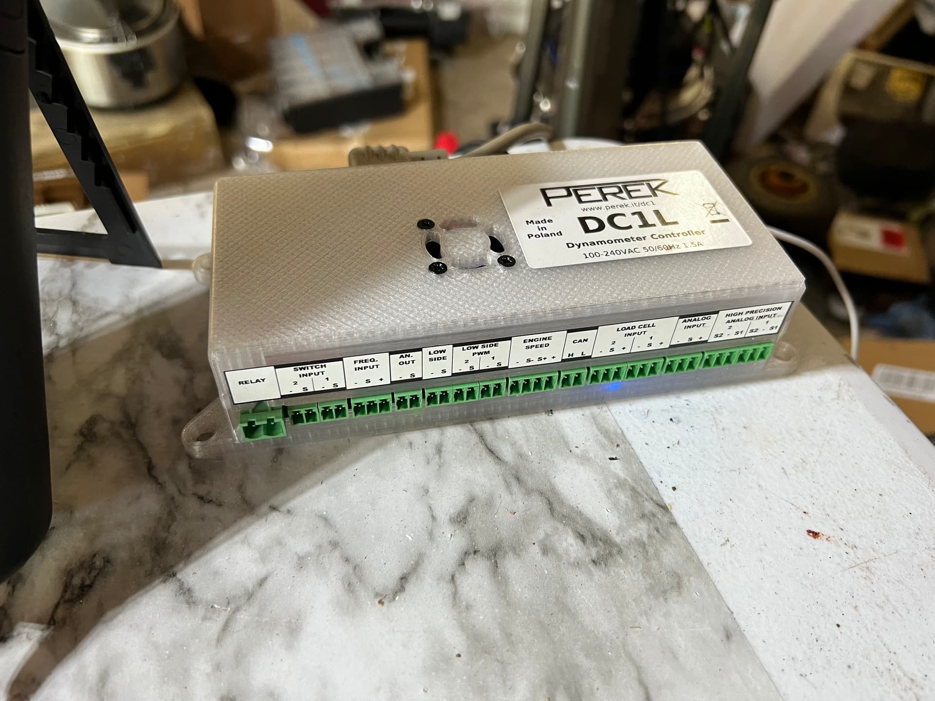
I’ve decided to skip using Ardyno and instead go with a Perek DC1L controller\logger. It offers so much for the money (about $750 landed) It’s impossible to pass by and will get me up and running with good results, faster:
Inertia dyno support (of course)
Toothed trigger wheel support for accurate control and readouts.
Load cell and brake controller support.
CANBUS support
Internal sensors for SAE (and other) power correction
A lot of potential for the coin
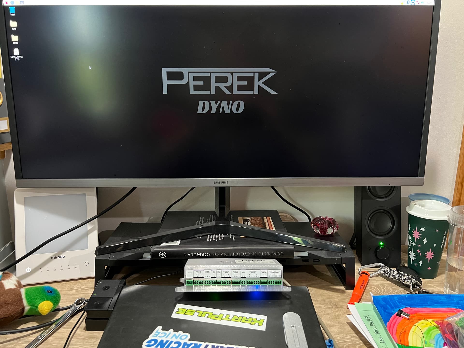
Dyno controller arrived from Perek in Poland just now and I am giddy as a kid ![]()
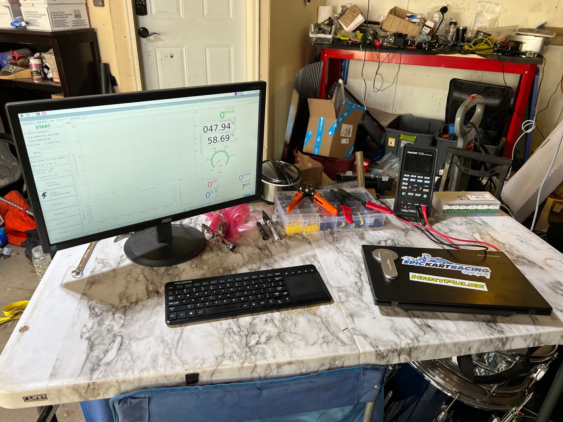
Took barely a week to arrive, detected my ultra wide display and keyboard without any fuss. It’s an all-in-on setup built on raspberry pi. You plug in your monitor and keyboard/mouse and go.
Forgot to mention the entire setup will run from solar/battery as there’s no power source at our storage/testing location and I can’t stand the drone of generators.
Updates before I head out of town for the weekend….
This week was spent wiring sensors, calibrating etc. Had a heck of a time with the ignition pickup. At first it was picking up 3600 RPM constantly (think 60hz). Turns out that was coming from the DC/AC inverter. For some reason the cable that came with the sensor was not shielded, so that probably didn’t help. Then picking up an actual signal was a challenge. On some engines it would need to be placed right by the coil, on another it only worked on the low voltage ground side of the coil ![]()
Long story short, I’m going to look for a different spark lead inductive (or maybe capacitive?) pickup. All I can say is that we are spoiled with the spark pickup in a Mychron.
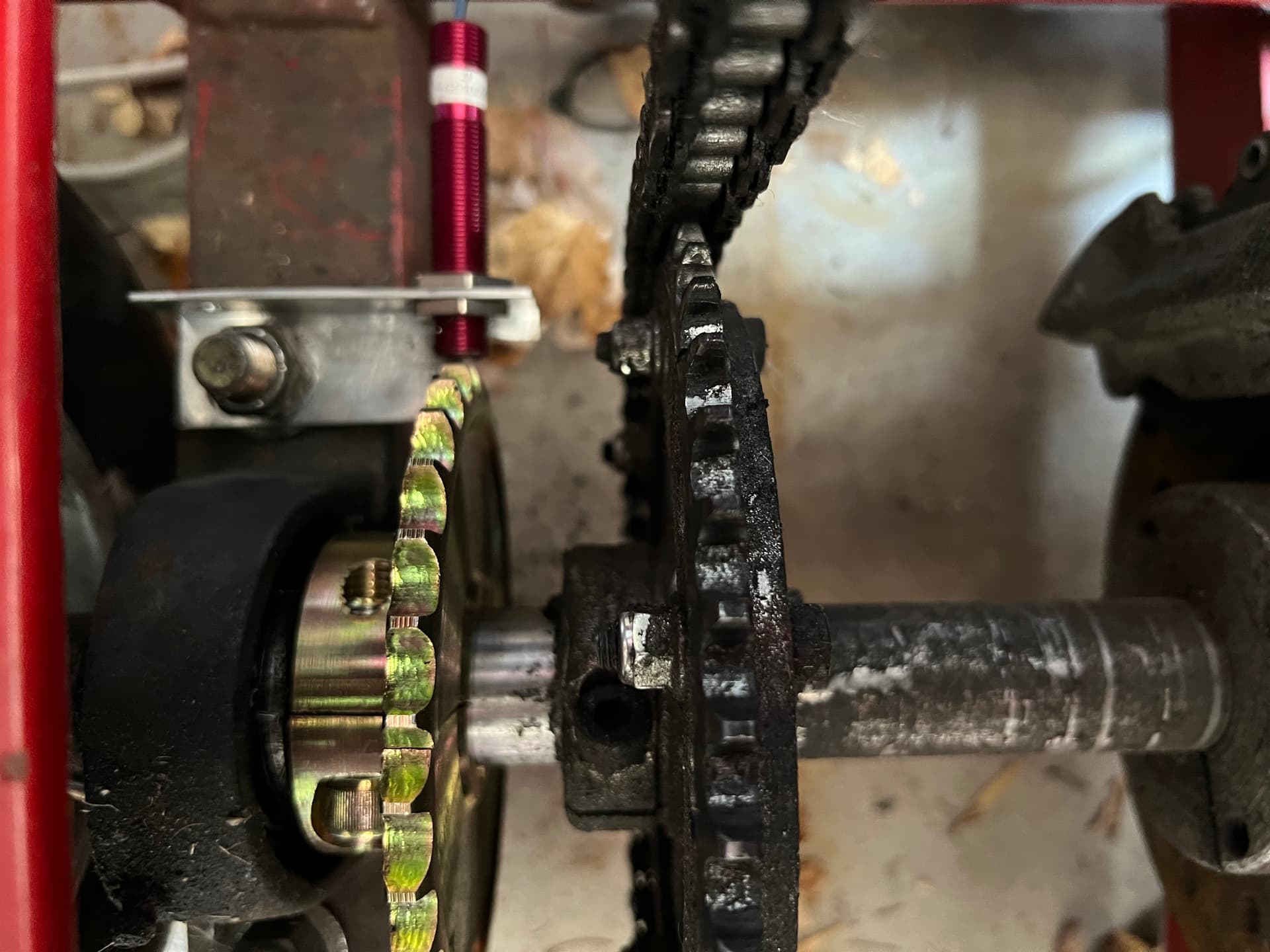
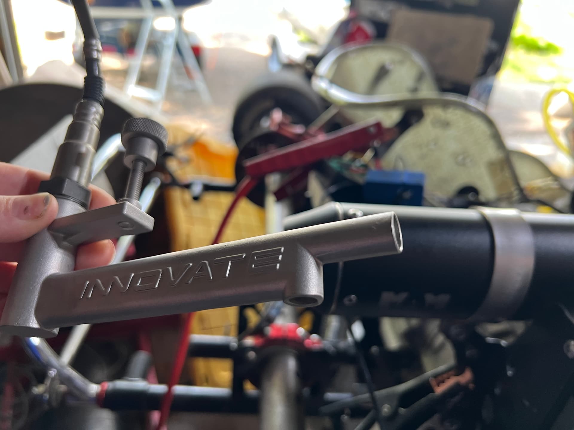
On the roller (road speed) RPM pickup side of things I ditched the original single tooth per revolution setup and “converted” to a 30 tooth by way of a 30mm, 30t 428 sprocket from the rental kart inventory and a hall sensor from Perek. 1 tooth is really not enough detail for an interia setup IMO and will be needed for a future brake controller setup anyway.
Temps for head and water/oil came together pretty easily since they are KTemp units (AIM/Mychron) and the Perek controller has built in support for those.
Main thing for the temp sensors was just getting the wiring done which meant I needed to order wire. Noticed the original wiring on the dyno was a shielded type by Belden. With prices approaching $900 for a roll of the stuff, I looked for alternatives. Turns out 4 connector alarm wire is also shielded, in the same gauge and available locally for $120. Grabbed a roll of that at Home Depot, ran the cable with the two channels down to 2x KTemp plugs and hooked up and good to go.
Lambda sensor took a little figuring out because the sensor ground needs to be on the same ground as the power source ground for it’s heater. Might be obvious to someone smarter than me, but it took a few goes before I was able to rule out the lambda controller as the problem due to the really strange voltages I was seeing when the signal ground and signal wires were hooked up to the terminals on the dyno controller.
For now the ground for Lambda heater power source is going through a relay in the dyno controller, then a jumper wire from the output of that relay goes to the analog Lambda sensor channel to meet the signal ground. This allows me to turn on/off the sensor manually via F5 key, a button on the screen or any method that I wish via the dyno software.
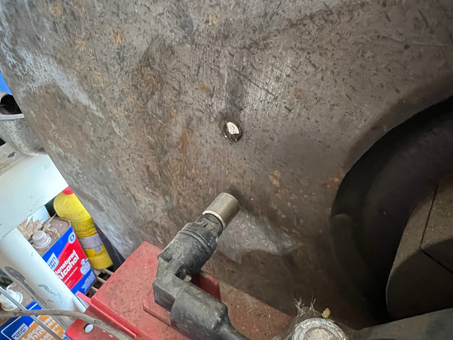
Calibrated the dyno via the falling weight method. It’s done by using a known mass (in my case a brake rotor at 10.2KG) to rotate the roller via a rope and pulley. The acceleration of the roller is logged and measured by the Perek software and it works out the moment of inertia based on the mass and the roller diameter. This was another bonus of having the 30 tooth trigger on the roller, great data to get a detailed acceleration curve for calibration.
The result was somewhere around 7Kg*M2 which is good for something like a 6 second pull at 70 HP. So I have more capacity than expected. It seems high though so I’ll likely re-run it before I take any readings seriously.
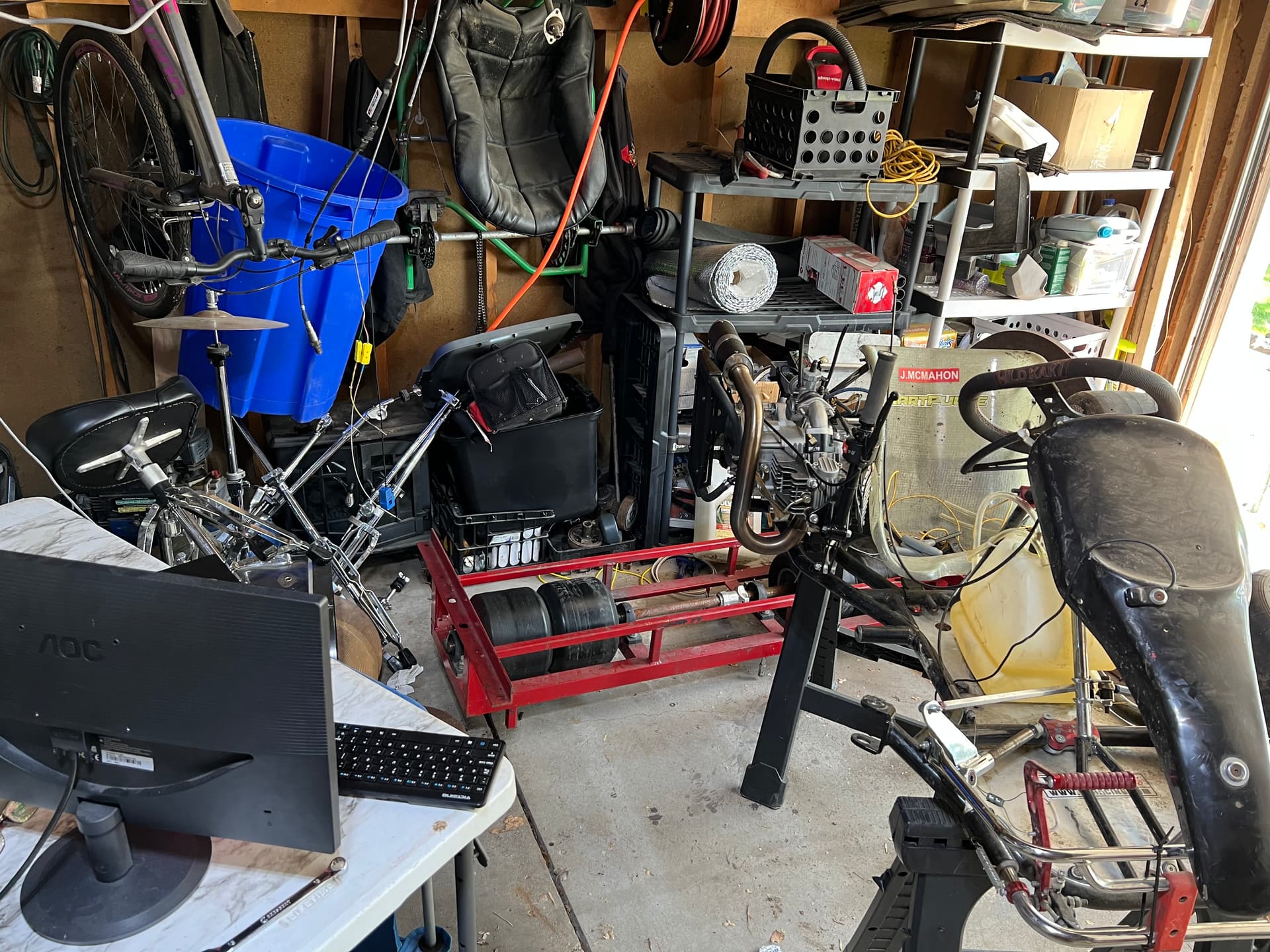
That’s about it for now. We’re still very much in mock-up mode in my garage before moving the setup to its home, so you’ll have to excuse the mess.
Goal for next week to is wrap all that up, get the dyno secured to the floor and move on to making an airflow meter to measure blowby. Then hopefully, finally, some dyno runs.
Some pics:
Perek dyno controller. Really liking this thing. Built on raspberry pi, so it’s light, reliable and boots fast. Built in sensors for SAE (and other) power correction, brake control support. It even has capability to run/replay and automate testing scenarios… ie… simulated laps which is a big plus because I intend to do some torture testing along the lines of 24hrs of straight running.
Thanks for sharing your adventures with your dyno with us all, it is very interesting reading all about it and hopefully it all works really good for you.
There is just so many things you could test with a dyno that you you just can’t do at a track to get meaningful results from.
You mentioned that you are making an airflow meter to measure the blowby of your engines I am curious on how you are going to do this.
After you get this to work could you share how you did it and where you hooked the air flow meter too.
Look forward to reading more on this DYNO venture.
For the airflow meter, probably easiest thing to do would be use a 28 (or smaller) throttle body with a MAP sensor and run that through a math channel. The MAP sensor would be a 0-5v analog signal, so it would use one of the two remaining analog channels I have. I can add more via CAN bus if I need to however.
Another option is to use something “fan” based by stripping out an anemometer and mapping the flow/voltage out for the same diameter pipe.
These are my best guesses so far. A traditional MAF sensor would probably spoil too quickly with whatever oil is in the crankcase gases. It would be the easiest to setup though, once I pick one with known scaling factor.
I think if plumbed correctly on the intake side, a MAF sensor would work best. As long as there is a bend in the intake tube to prevent oil/gas spitting back from the carb into the sensor, you shouldn’t have any issues with fouling it. Since most modern two strokes have reed valves, you may get weird readings on a MAP sensor. At best you could measure peak and trough values along with their frequency then try to use a math function and calculate actual air volume. MAF sounds simpler and more straight forward.
Just a thought. Let us know how it works out.
Remember this is for engine/ring blowby on four strokes. Not intake (although I will come to that at some point, it’s a little easier too)
I recon the blowby gauge is going to take a few iterations to see what’s best, unless I’m willing to throw down over $1000… which I’m not totally opposed…
I guess I could try and source a MAF sensor with a small housing and a known scaling curve, protecting the sensor from oil in some way. (Accepting recommendations on a small housing). Luckily consistency is more valuable than accuracy, but I really would prefer to have an accurate system ![]()
That’s basically how it works using a differential pressure sensor in a known size restriction. In some cases people just use the MAP reading directly to measure crankcase pressure vs trying to work out flow.
Of course I wouldn’t need the Arduino, I’d just pull the two 0-5v signals into the dyno controller and create a math channel in the Perek software.
I think my favorite would be to use is to use the fan/anemometer method since I don’t have to worry about fouling, just maybe an occasional cleaning… But I’d be on my own for calibration.
There’s this method too which works great, but I’d rather have something that logs along with the rest of the data…
Actually… looking at the sensor prices again… I might just buy one …$649. I think this data is essential and often overlooked.
https://www.performancetrends.com/prices.htm#Blow_By_Blowby_Sensor_Prices
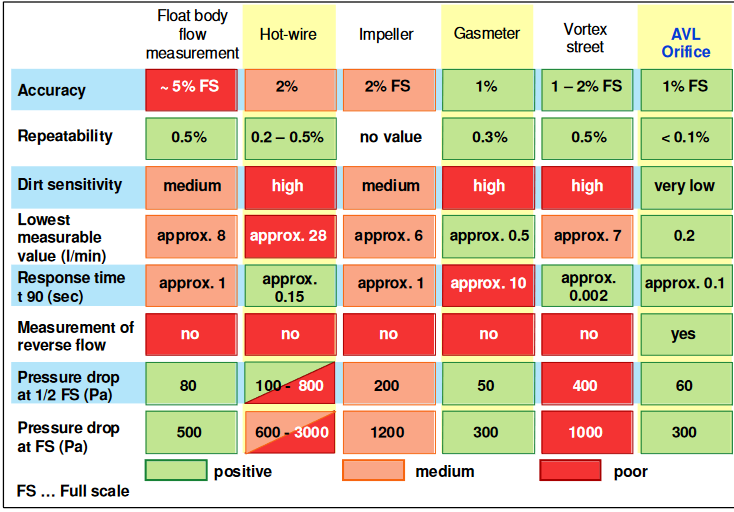
Found this interesting…
From:
https://www.avl.com/documents/10138/2699442/AVL+Blow+By+Meter+Product+Description
Lambda sensor “sniffer”’arrived today. As I expected it’s too big for use on kart applications, so I’ll use it as a base for a smaller setup that’s more suited for the confines of karting exhausts.
Maybe add an extension pipe to the inlet side to get to the middle of the pipes, then pull a vacuum from the outlet.
Progress has slowed a little with other projects taking focus but still chipping away.
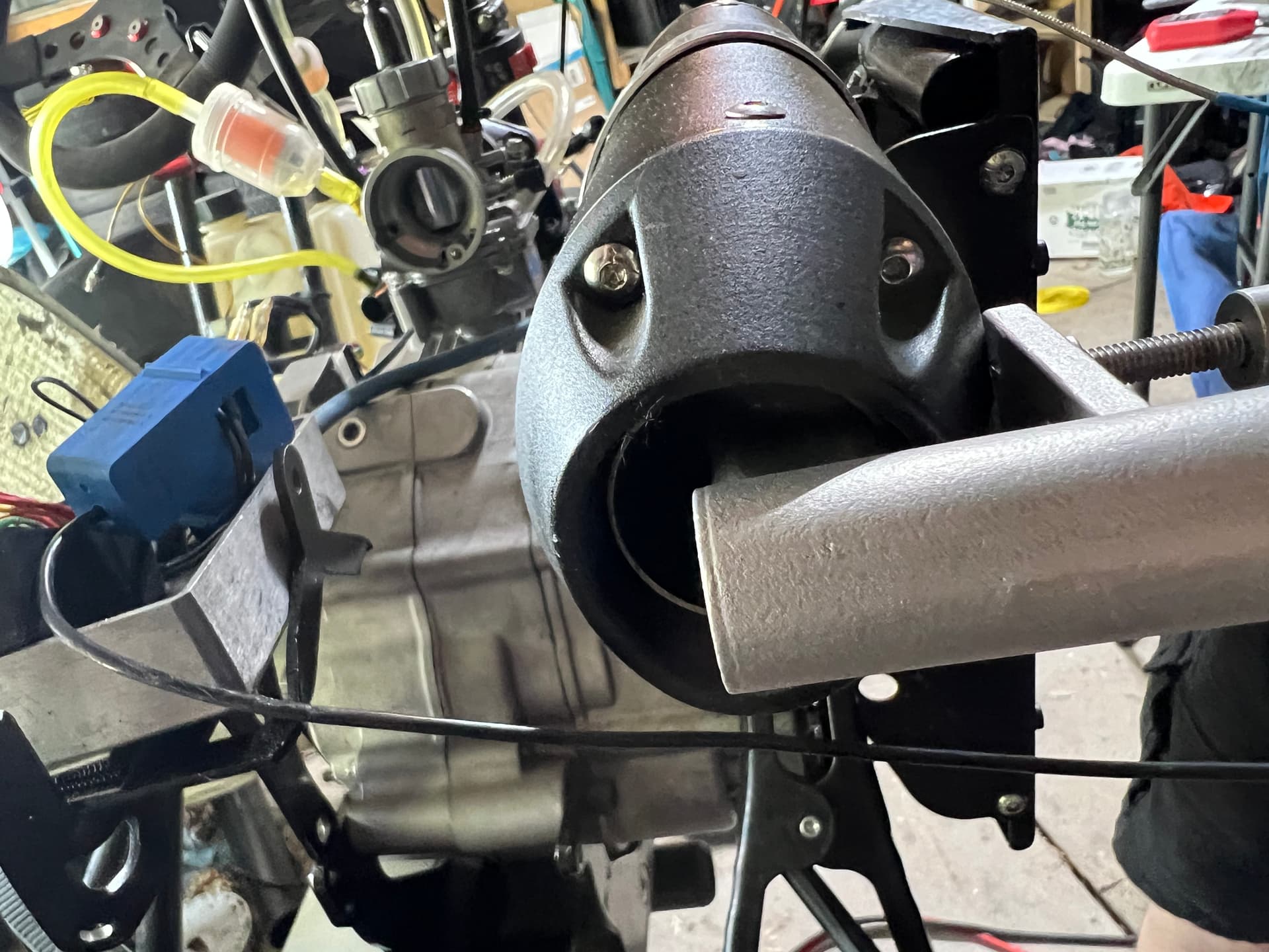
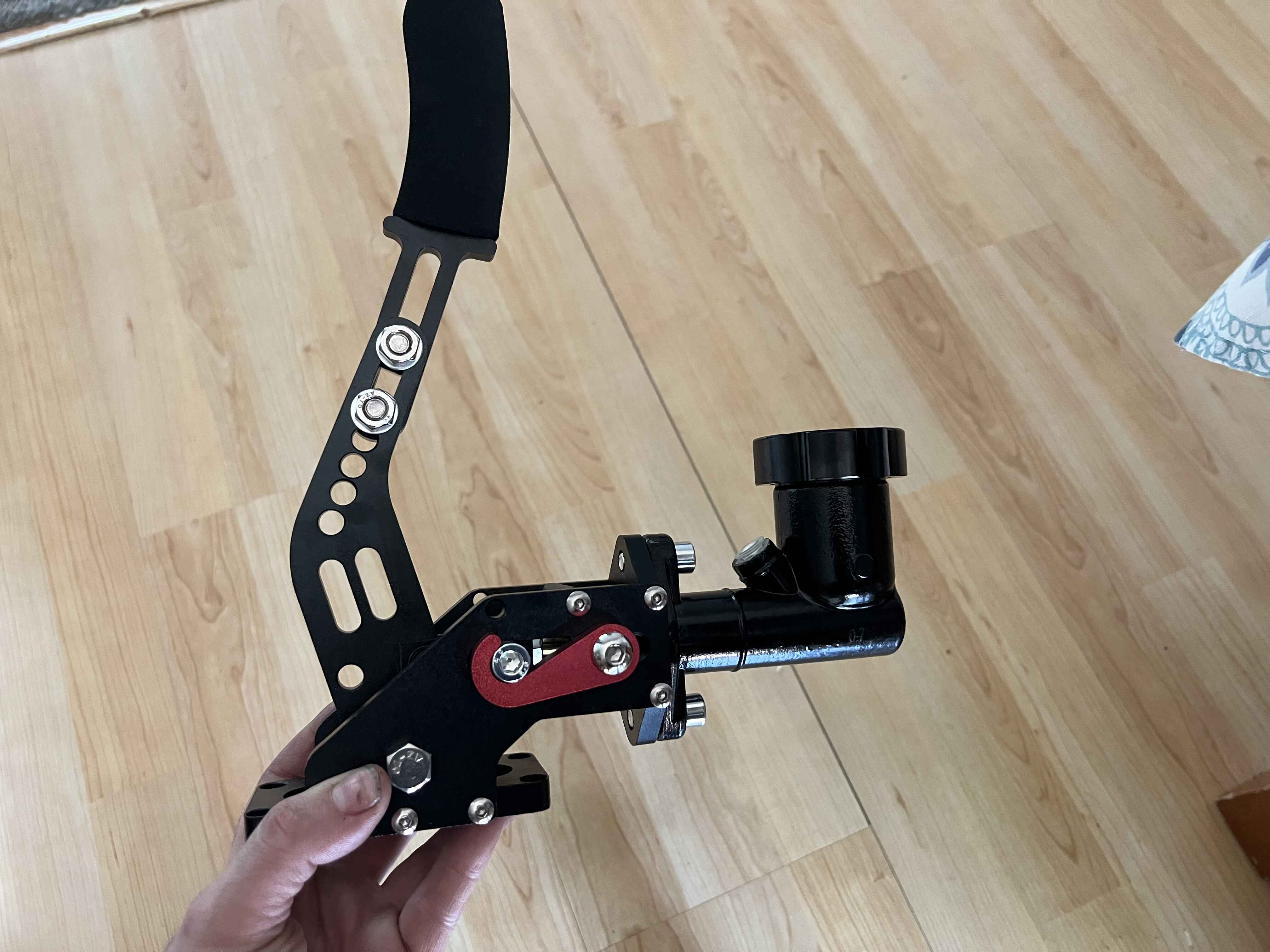
Bought a hydraulic handbrake so that it’s easier to lock the roller when mounting and strapping down a kart.
Also got a 2BAR MAP sensor hooked up for crankcase pressure. Yet to see how that will work out.
The goal is to turn it into a mobile dyno mounted to a trailer. Still looking at different trailer options to see what might work best.
A utility trailer seems to be a good way to go. Length wise I’m thinking between 12 and 14ft long so I can fit at least two karts end to tail on the trailer too.
Looking forward to this. As impossible as it is to find any dyno charts for common kart engines, this could be a great help in understanding where they really make their best power.
James, have you made any further progress on your dyno project in the last 6 months?
Yes! I managed to cover it with tubs of equipment and spares from the rental karts ![]()
I will pick it back up at some time over summer perhaps.
The engines on the rentals got some love over winter and the plan was to make a bracket to test and break them in on the dyno. But other things have taken priority for now.
Totally understand that. Side projects always have to take a backseat to what everyday life throws at ya!